OS Installation
This guide covers the generic setup of an RC controller (RX) for a drone. Different RCs might have various switches and buttons in different positions.
Requirements
- If ELRS is being used, update both the RX and the TX to the newest version, RX and TX have to have a matching version of ELRS
- RX and TX is paired and connected to the FCU
- QgroundControl is connected, and radio channels are visible in the Radio tab
Step 1: Setup the main 4 RC channels
The first 4 channels correspond to the stick controls. They need to have this fixed order, which is expected by the MRS System:
| Channel | Function | Description |
|---|---|---|
| 1 | Roll | manual input |
| 2 | Throttle | manual input |
| 3 | Pitch | manual input |
| 4 | Yaw | manual input |
This order of channels is critical, and has to be kept irrespective of Mode1/Mode2
Most RCs do not have this channel order by default, some outputs have to be switched. To switch Outputs, navigate to the Model menu of the RC, scroll to the MIXES tab, and switch around the inputs to the correct channels.
Step 2: Setup the next 4 RC channels
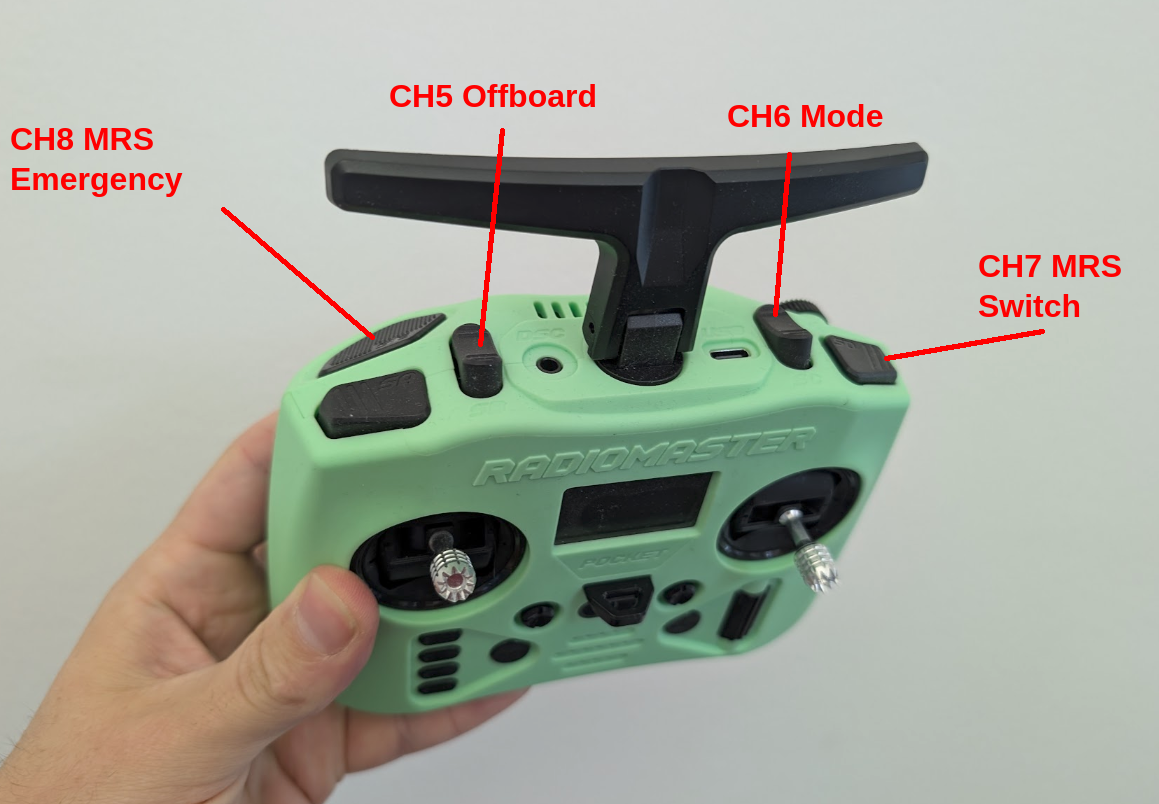
Channels 5-8 are used for switching of flight modes, offboard mode, and as signals to the MRS System. They have to follow this table:
| Channel | Function | Description |
|---|---|---|
| 5 | Offboard | offboard switch - give/take control to/from the MRS system |
| 6 | Mode Switch | 3-position switch, which switches between Manual/Alitude/Position PX4 flight modes |
| 7 | MRS Switch | Switch that signals for the MRS System that remote mode should be activated |
| 8 | MRS Emergency | momentary signal that signals to the MRS System that it should trigger an emergency response (ehover/eland/failsafe/disarm, according to config) |
- Channels 5 and 6 are used in PX4, and should be configured in QGroundControl flight modes tab, according to this table
- Channels 7 and 8 are only signals for the MRS system, no PX4 functionalitno PX4 functionality should be tied to them
- Channels 9 and higher can be used for any other purpose
Physical RC setup
- First 4 channels are mapped to the main sticks, either Mode1 or Mode2, according to the client preference
- Channel 5 (Offboard) has to be a 3-position or a 2-position switch, in the middle left of the RC
- Channel 6 (Mode Switch) has to be a 3-position switch, in the middle right of the RC
- Channel 7 (MRS Switch) has to be a 3-position or a 2-position switch, in the far right of the RC
- Channel 8 (MRS Emergency) has to be a momentary switch/button, in the far right and down of the RC
Momentary switch means the signal is asserted only when switch/button is held, it is deaserted once the switch/button is released.
If the RC does not have the switches in the correct places, try to match the positions as close as possible, and make sure to document the layout for the customer. Here are some examples of switch layouts:
On the Radiomaster pocket, the only momentary switch is on the left, so we have to use it for the CH8.