RoboCore Arm Build Guide
Overview
This guide covers the full assembly process for a RoboCore arm. Two arm lengths are generally available:
| Variant | Carbon Tube Length |
|---|---|
| 22 in | 350 mm |
| 18 in | 300 mm |
Required Parts
Hardware
| Item | Specification | Quantity | Notes |
|---|---|---|---|
| Motor | — | 1 | Choose varient based on the arm length |
| Carbon tube | 350 mm or 300 mm | 1 | Cut to size per variant |
| Bolt | M3x25 | 4 | Lower motor mount holes |
| Bolt | M3x6 conical head | 2 | Outer insert fastening |
| Nut | M3 | 2 | Inside XT60 (inner) insert |
| Large nut | M3 (arm nut) | 1 | Outer insert retention |
| Blue threadlocker | Loctite or equivalent | — | Applied to motor holder bolts |
| Super glue | — | — | XT60 connector bonding |
Electronics & Cables
| Item | Notes |
|---|---|
| Motor cables | Cut to arm length using cable cutter jig |
| 3-pin XT60-style connectors | 1 per arm |
| Heat shrink tubing | For motor cable connections |
3D-Printed Parts
| Item | Notes | Type |
|---|---|---|
| Triangle piece | Slides onto cable bundle | FDM |
| XT60 insert | Inner plastic insert with M3 nut pockets | SLS/FDM |
| Cable adjustment piece | Slides onto cable bundle | FDM |
| Upper motor mount | Accepts 1 mm carbon plate with hole | SLS |
| Lower motor mount | Accepts 2 mm solid carbon plate | SLS |
| Inner plastic inserts | Pushed through carbon tube | SLS |
| Outer plastic insert | Secured through tube to inner inserts | SLS |
Carbon Plates
| Item | Quantity | Notes |
|---|---|---|
| 1 mm carbon plate with hole | 1 | Upper motor mount |
| 2 mm solid carbon plate | 1 | Lower motor mount |
Jigs
| Item | Quantity | Notes |
|---|---|---|
| Cable Cutter Jig | 1 | Two possible cable lengths available |
| Tube cutter jig | 1 | Look up saw cutting jig over our drill press |
| Tube drill jigs | 2 | 3D Printed blocks on each side of the tube. Follow instructions on them |
Assembly Steps
Step 1 — Cut the Carbon Tube
Cut the carbon tube to the appropriate length for your variant:
- 22" in variant: 350 mm
- 18" in variant: 300 mm
Step 2 — Attach the Drilling Guide Tool
Attach the guide tool to both the body side and the motor side of the tube. Make sure the square ends are parallel — use a flat table to align them.
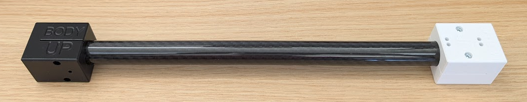
Important: The guide blocks are marked with UP and DOWN sides. The drilled holes must be orthogonal to each other on each respective side.
Step 3 — Drill the Holes
Using a 3.2 mm drill bit, drill through all guide holes in the tool:
- Body side: 2 holes
- Motor side: 8 holes
Important: Use water, a wet tissue, or a vacuum at the guide holes to prevent carbon dust from becoming airborne.
Step 4 — Connect Adjacent Motor-Side Holes
Connect two adjacent holes on the motor side of the tube.
Missing picture Motor side hole connection.
Step 5 — Clean the Holes
Thoroughly clean all drilled holes and remove any remaining carbon particles.
Step 6 — Check Plastic Inserts
Dry-fit all plastic inserts to confirm they seat correctly in the tube before proceeding.
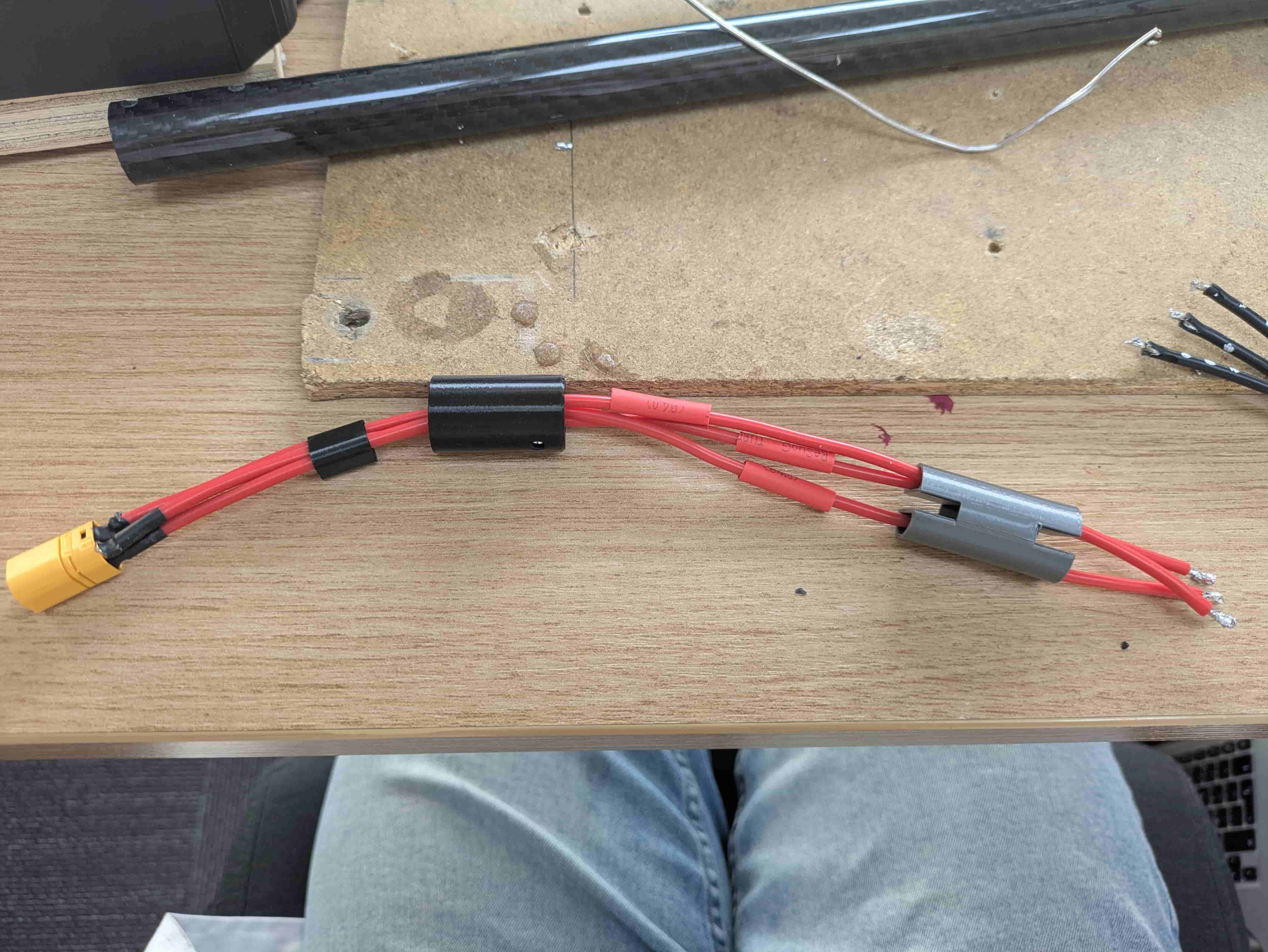
Step 7 — Prepare the Cables
Cut the cables to the length of the arm using a cable cutter jig, then strip the ends. Solder the cables to 3-pin XT60-style connectors and apply heat shrink tubing.
Slide the 3D-printed parts onto the cables in this order:
- Triangle piece
- XT60 insert (place two M3 nuts inside the inner plastic insert beforehand)
- Cable adjustment piece
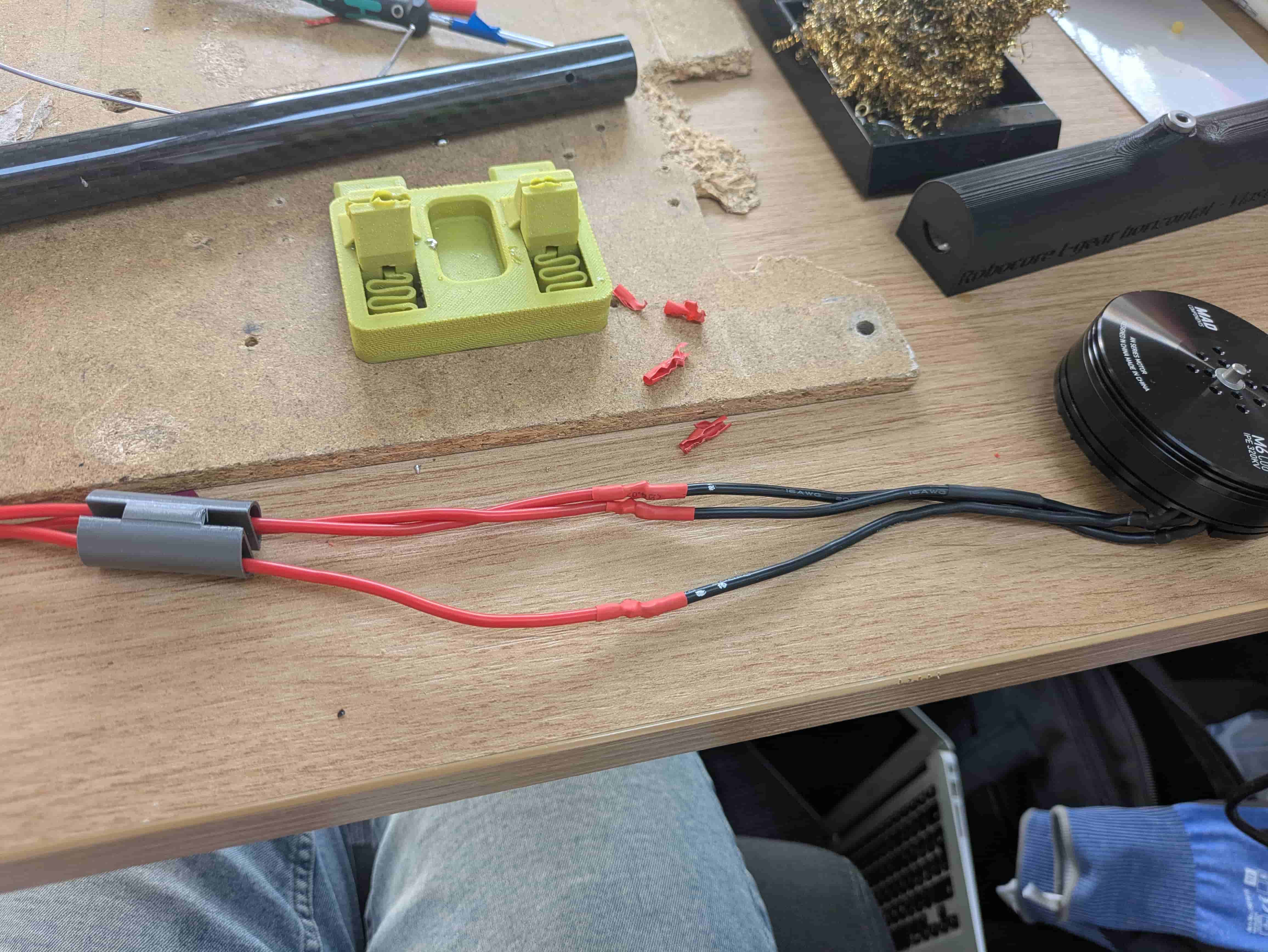
Step 8 — Solder Cables to the Motor
Before soldering, ensure heat shrink tubing is already placed on each cable. Solder the cables to the motor but do not shrink the tubing yet. Position the heat shrink over the bare connections and verify that no cables are touching each other.
Use the RoboCore Arm Tester to check the motor spin direction. If the motor spins in the wrong direction, swap two cables and test again. Once the direction is confirmed correct, shrink the heat shrink tubing.
Step 9 — Insert Plastic Inserts into the Tube
Take the prepared carbon tube and push all plastic inserts through it.
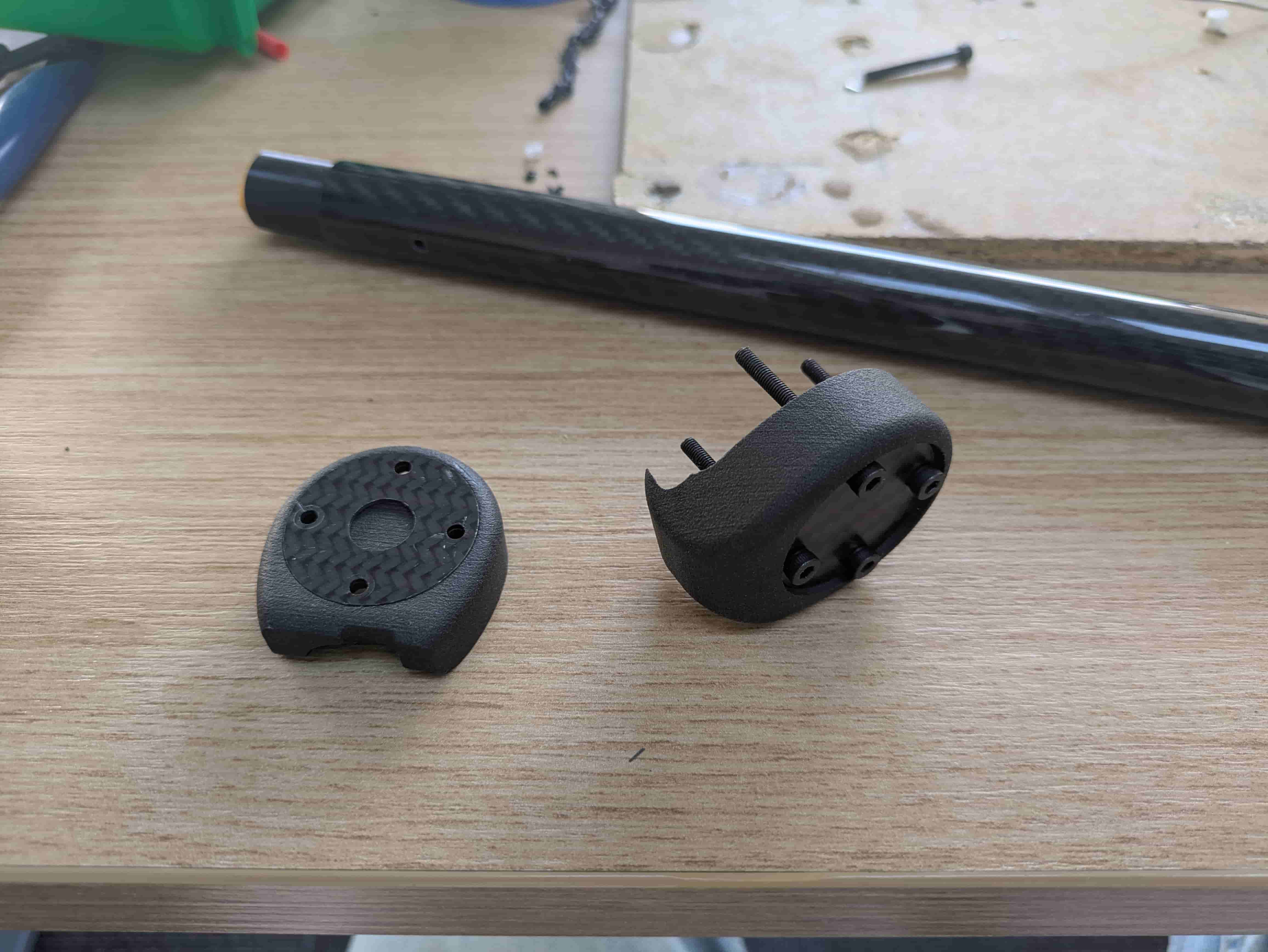
Step 10 — Prepare the Motor Mount
Take the upper and lower motor mount parts and insert the carbon plates into their slots:
- Upper mount: 1 mm plate with a hole
- Lower mount: 2 mm solid plate
Place M3x25 bolts into the lower mount holes.
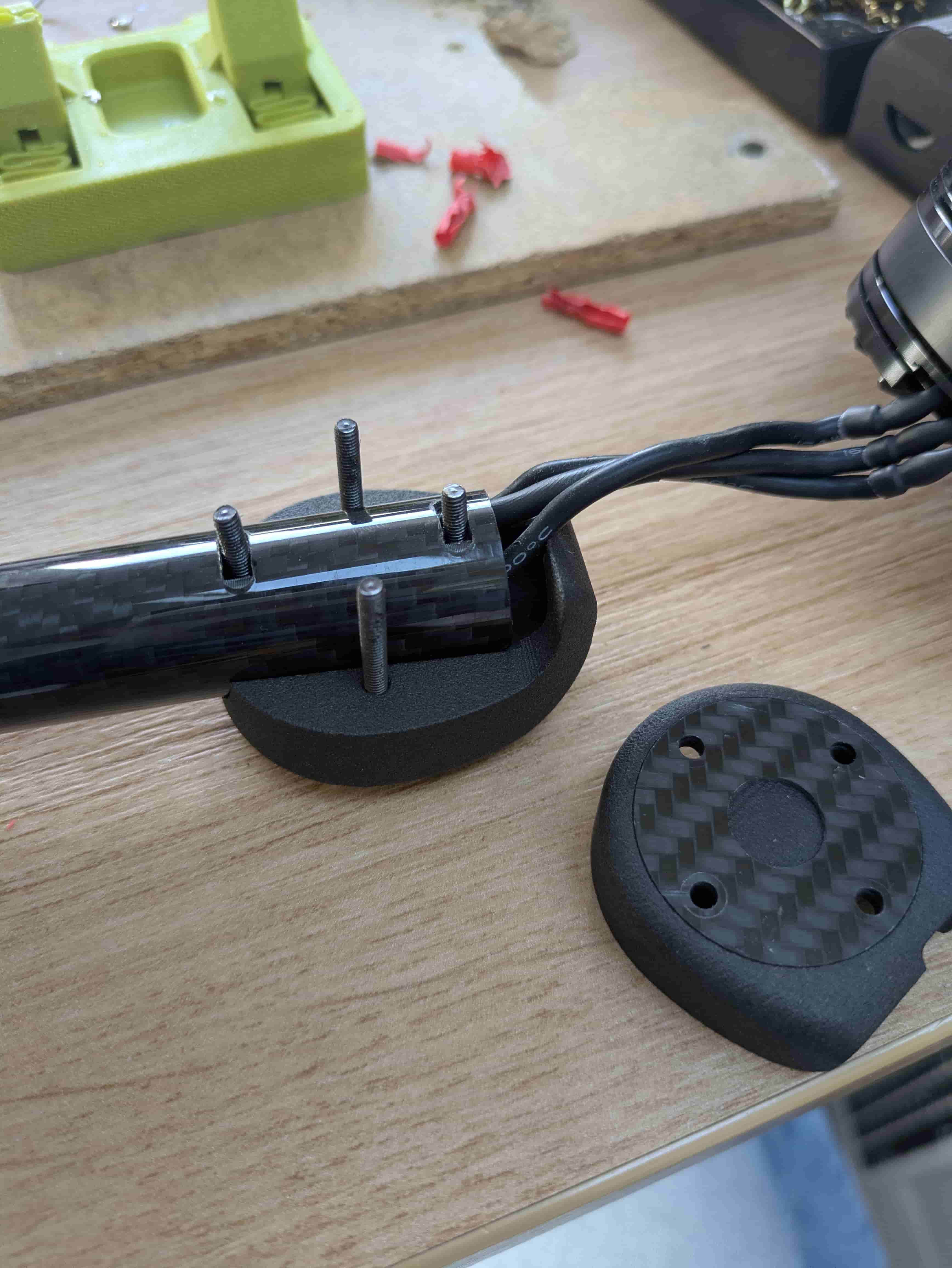
Step 11 — Mount the Motor Holder
Slide the lower mount onto the motor side of the tube and the upper mount onto the body side.
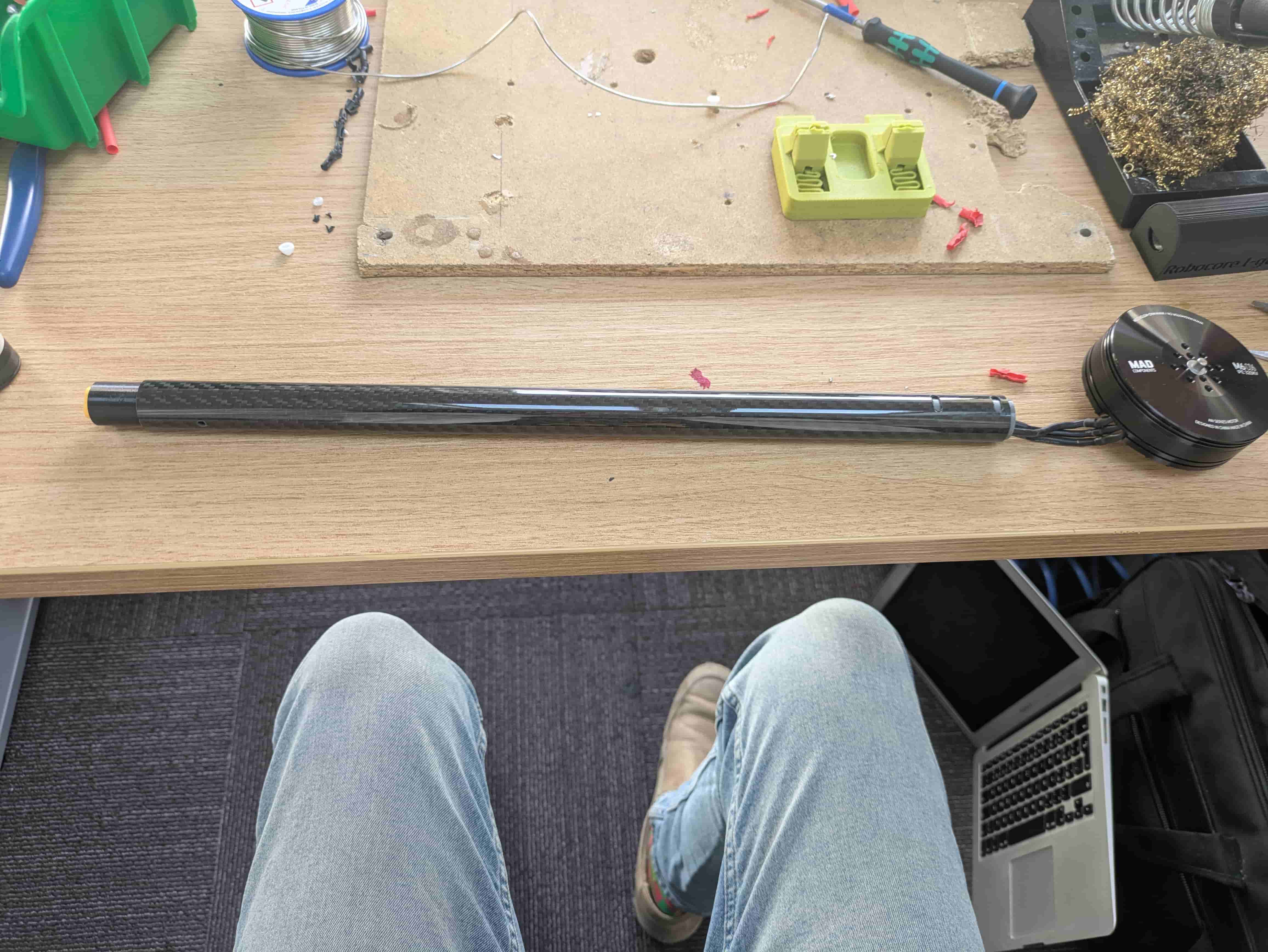
Step 12 — Attach the Motor
Route the cables so they are as short as possible, then attach the motor to the arm and tighten all bolts. Apply blue threadlocker (Loctite) to the bolts before tightening.
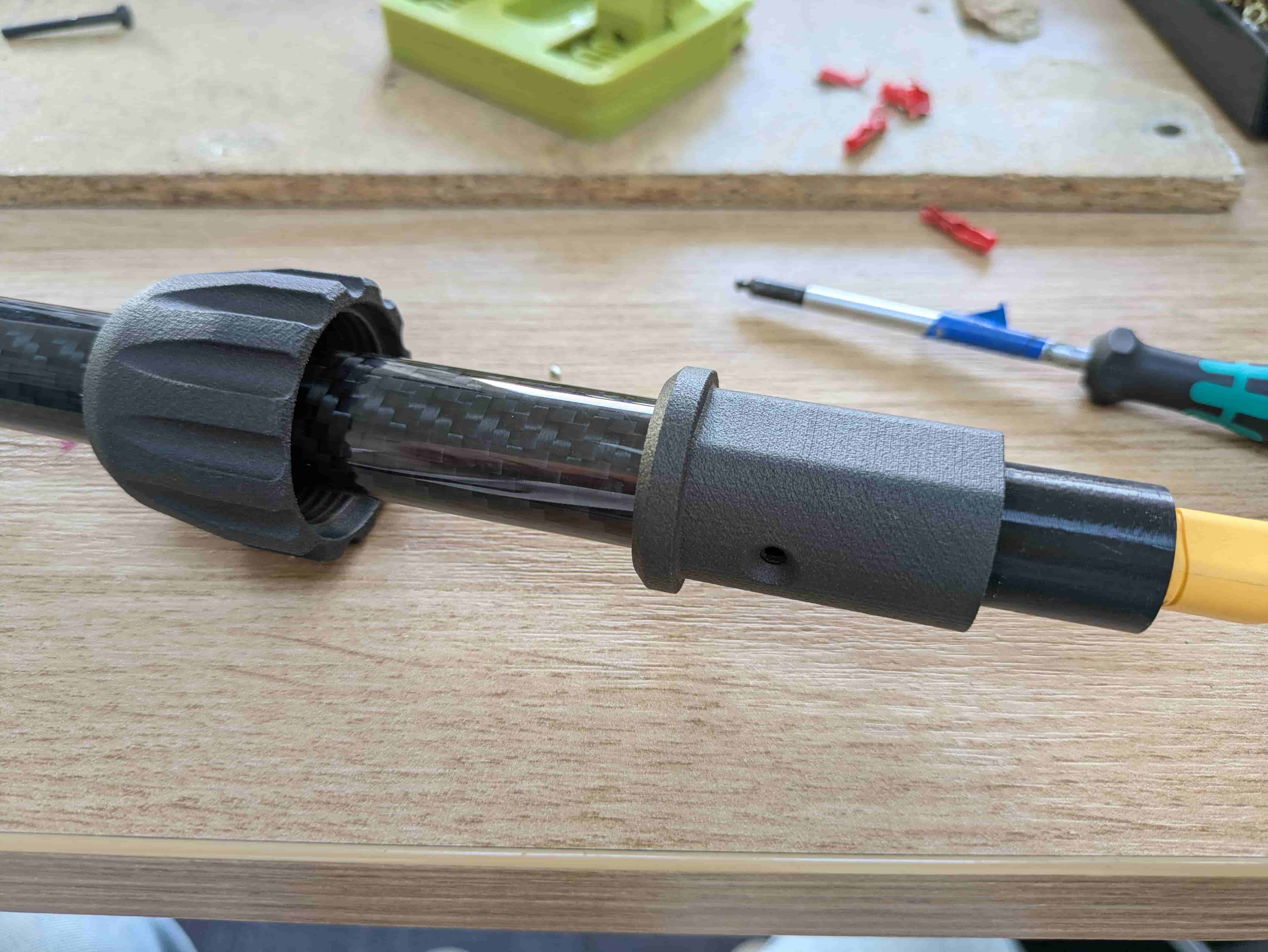
Step 13 — Secure the Outer Insert
Place the large nut onto the arm, followed by the outer plastic insert. Position the insert so it aligns with the holes in the carbon tube. Insert an M3x10 countersunk bolt and fasten the outer insert through the carbon tube into the inner insert nuts.
Note: The flat face of the outer insert should point upward, toward the motor side.
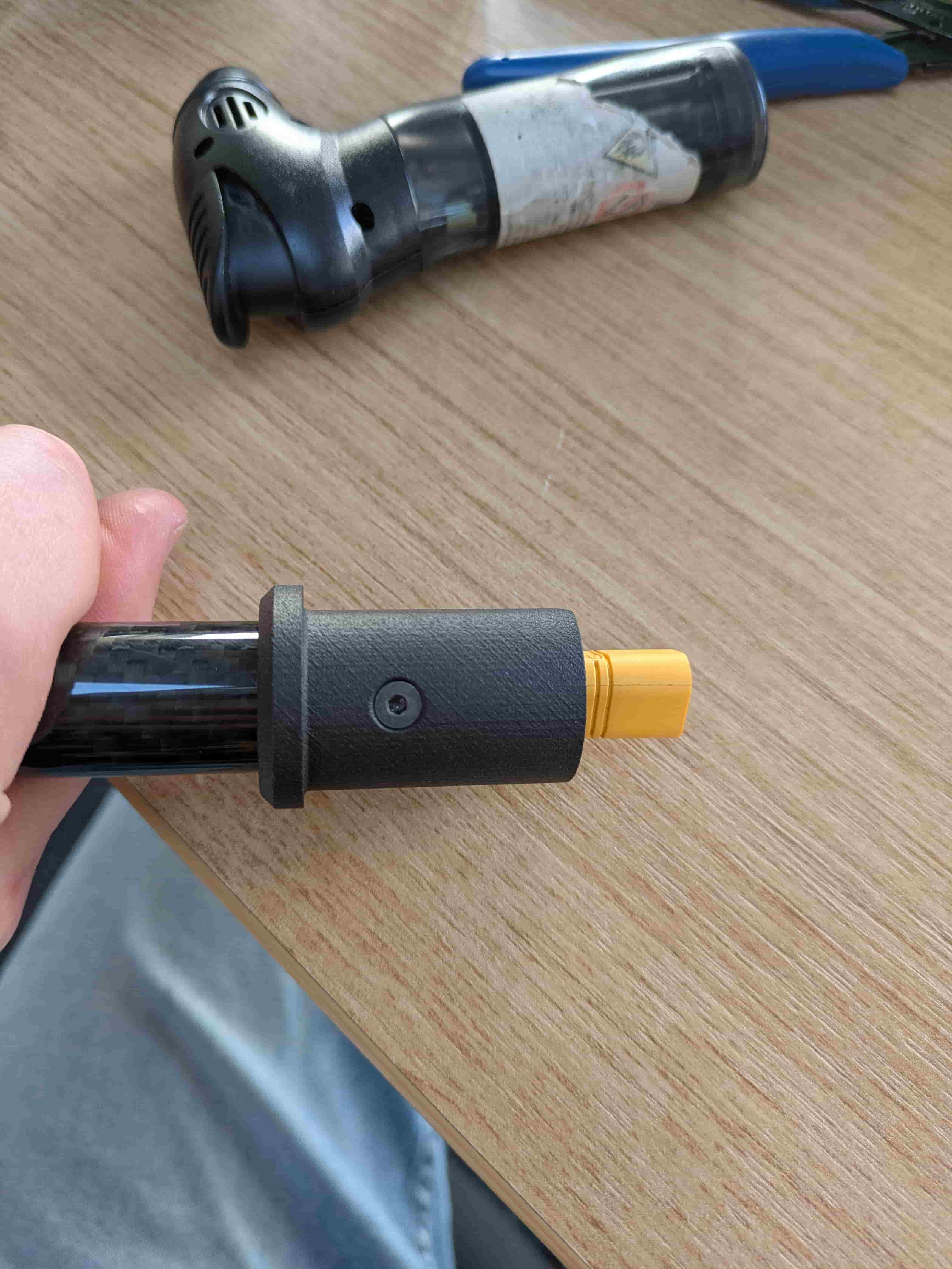
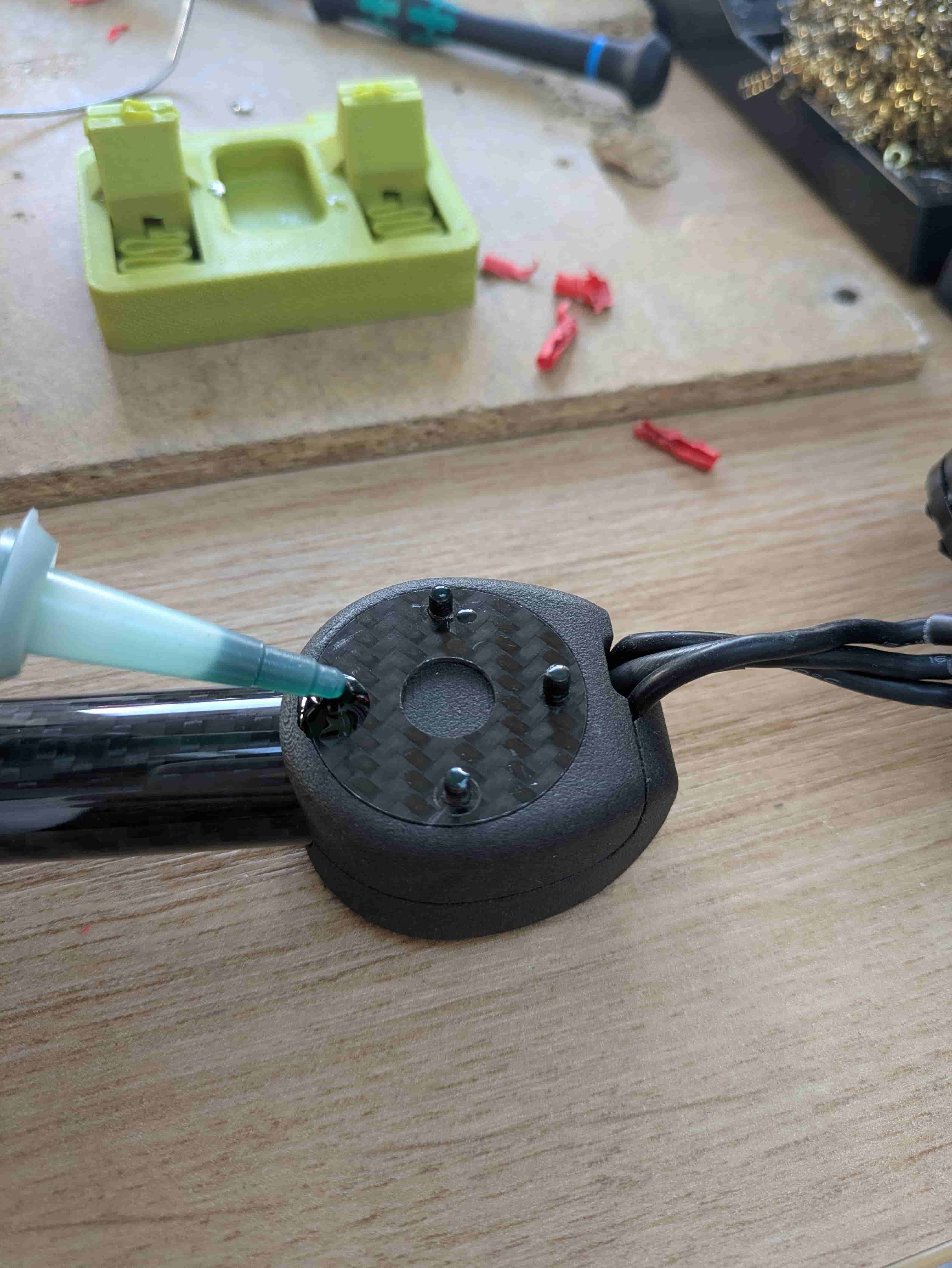
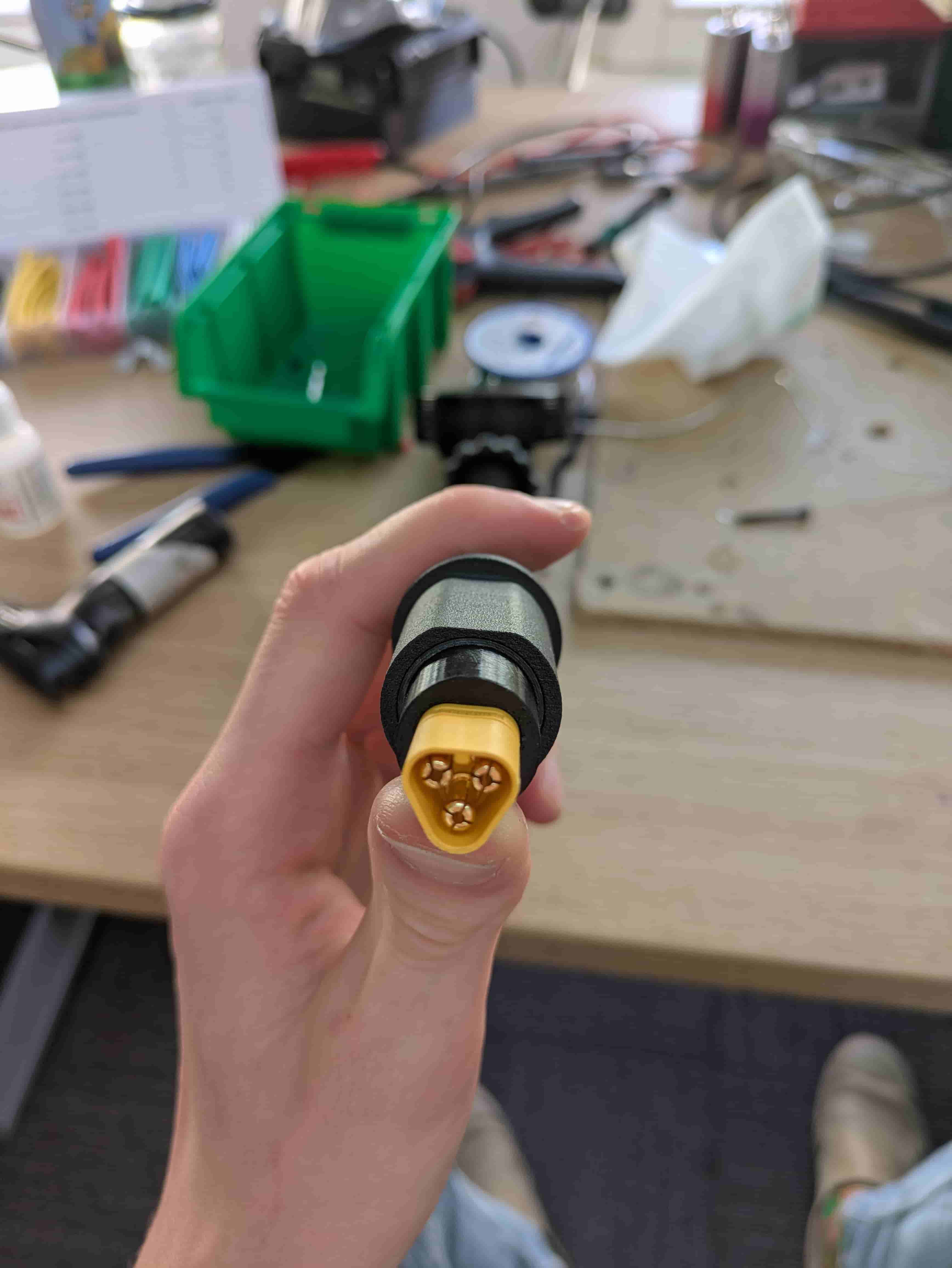
Step 14 — Glue the XT60 Connector
Apply a small amount of super glue to all sides of the XT60-style connector and press it firmly into the inner insert, oriented as shown.
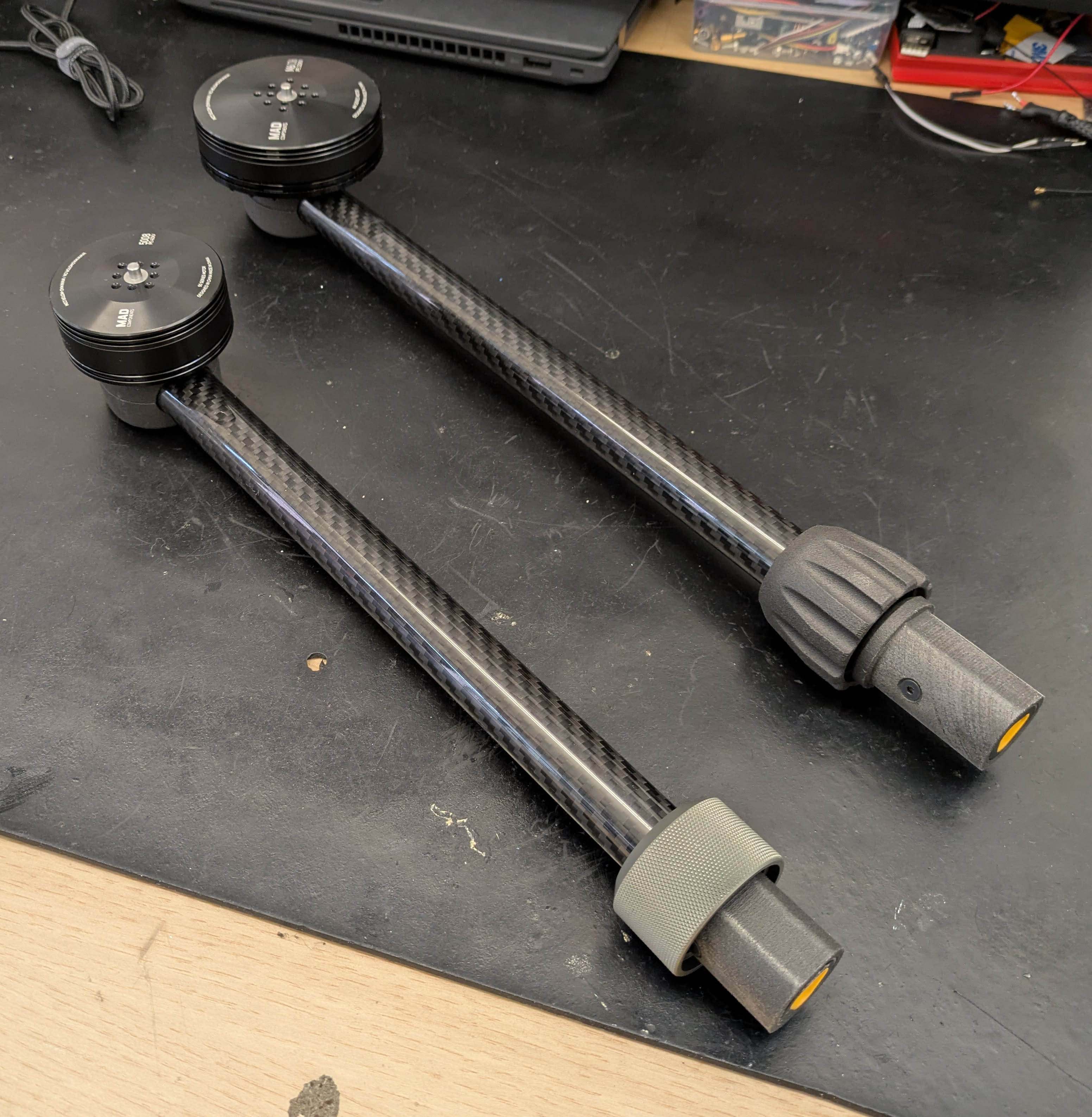
Step 15 — Assembly Complete
The arm is fully assembled.
Thank you for following the assembly guide!