Motor Cable Fix
Robofly can suffer from broken connections between motor cables and the ESC. This is caused by two factors:
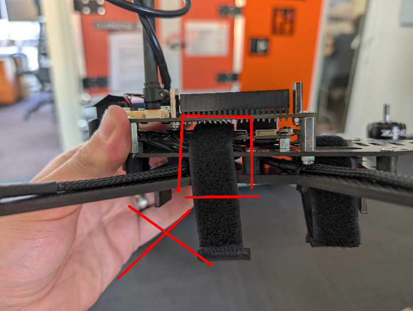
- Incorrect placement of the Velcro that secures the battery, which pulls on the motor cables
- Motor cables being too tight (because they are short)
We will address both of these issues here.
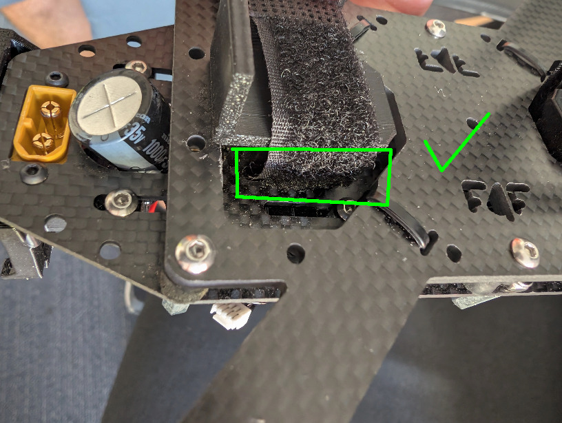
Velcro fix
The fix is simple, just run the velcro Under the ESC, through the slots which are cut in the CF plate. You can remove the ESC for easy access, but it is possible to run the velcro even with ESC attached, with a help of tweezers, pliers and some finesse.
Motor cables too short
We can increase the slack of the motor cables by moving the ESC forward, as it is mounted in slots and movable.
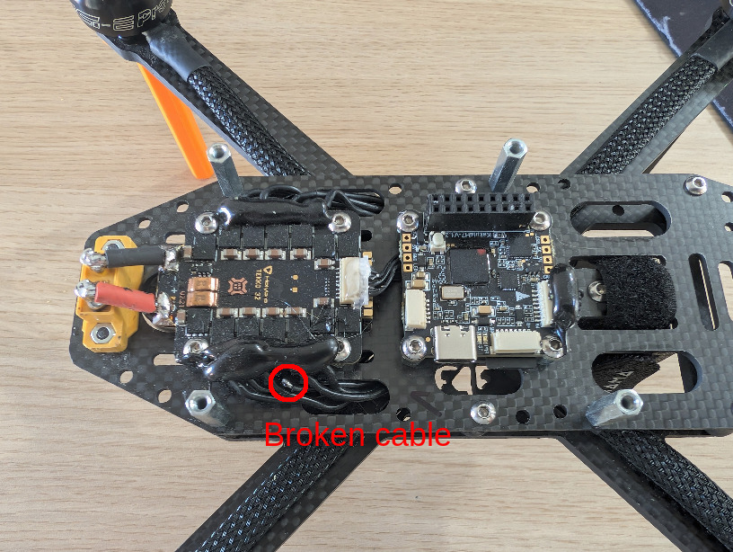
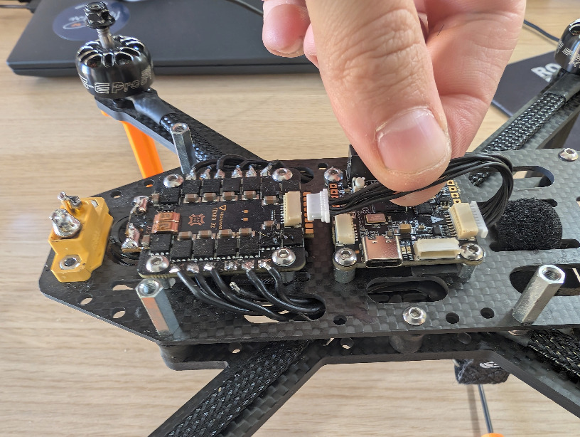
1: Remove the distribution board, so that we can access the ESC:
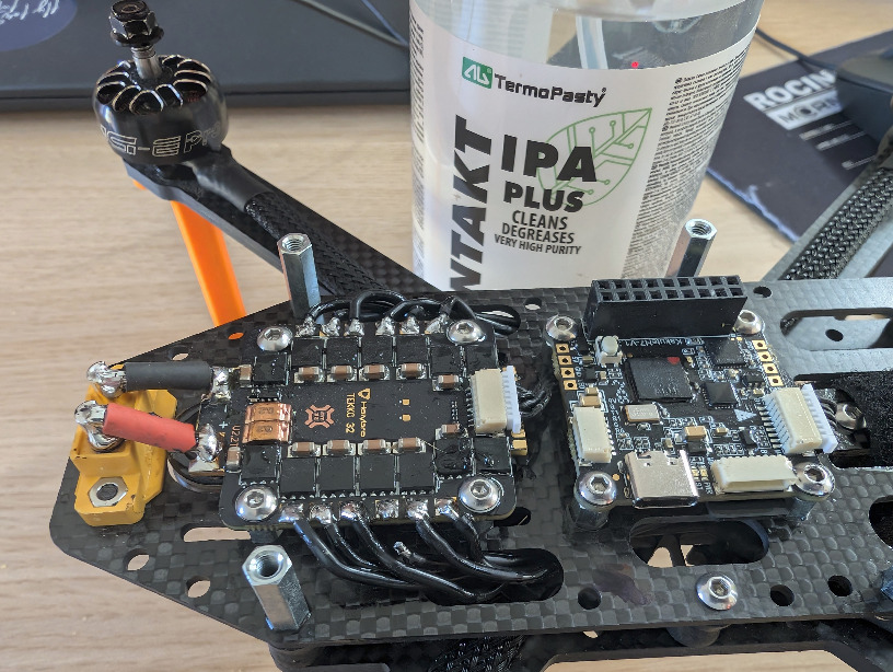
2: Remove the previous hot glue, to access the cables. Use IPA for easy hotglue removal.
3: Connect a male XT60 into the battery connector (to prevent melting) and then desolder the power cables from the ESC.
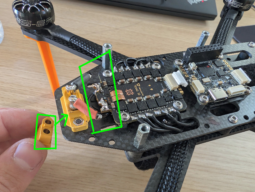
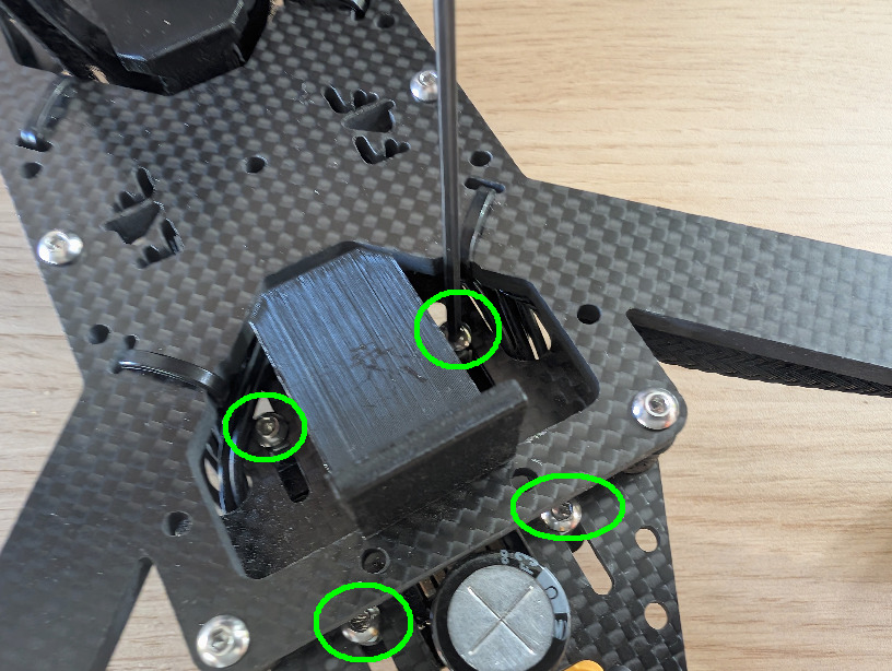
4: Unscrew the 4 bolts holding the ESC from the
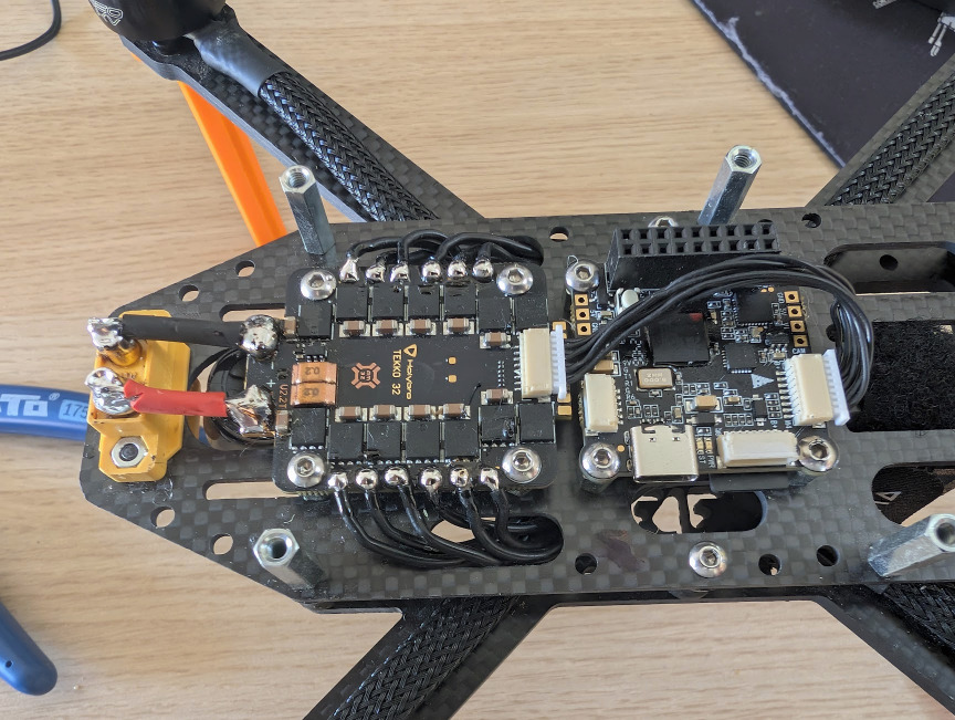
5: Disconnect carefully the ESC signal cable, and run it over the FCU (it was ran under the FCU before). Carefully reconnect the cable to the ESC.
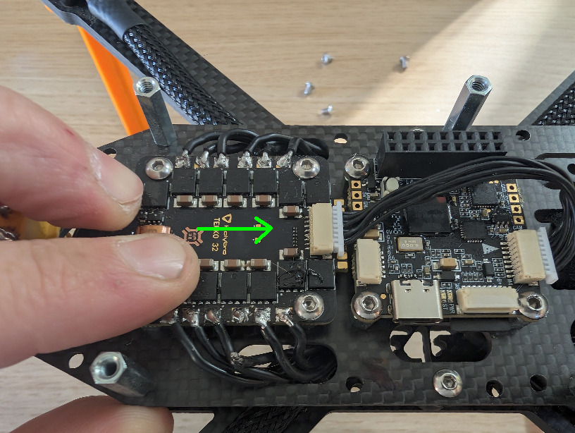
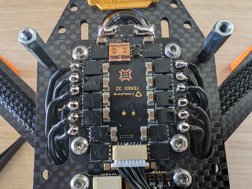
6: Push the ESC forward, towards the FCU. Keep a small gap between the ESC and the FCU (1mm is a good gap). You will need to bend the ESC capacitor a little, this is fine.
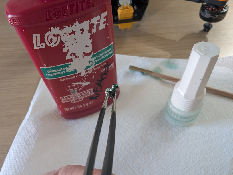
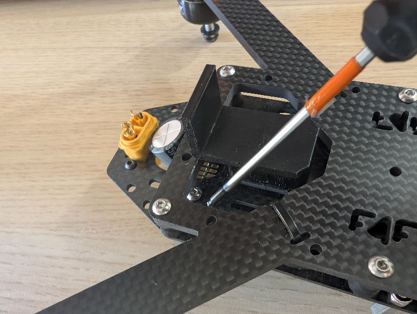
7: Now reattach all 4 bolts of the ESC, while keeping the ESC pushed forwards. Use Threadlocker to secure all the bolts. Use a ball-end hex driver to reach the bolt from the side.
You can use this time to check all the other bolts for loosesnes, if you find anything suspicious, retighthen all the bolts while using threadlocker.
8: With the ESC fixed in place, resolder all the motor connections. Use plenty of solder and flux, and make sure that the solder joint is properly heated-through. Your solder joints should look like the following photo. If they do not, ask Dan H. how to achieve such joints:
9: Resolder the Power connection with longer cables. Use at least AWG12 cables.
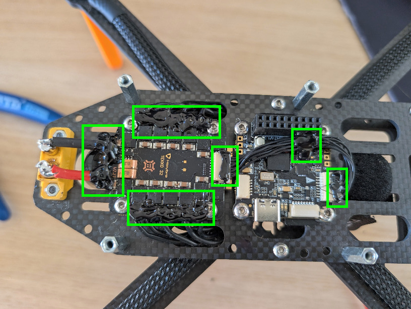
10: Test that all the motors spin correctly. If they do, cover the following areas with black hot-glue:
- ESC power connection
- ESC motor connections
- ESC signal cable
- FCU signal cable
- Attach the signal cable to the FCU as shown
11: Reassemble the rest of the UAV, do a test flight.