F9P Helical
Required Hardware
- F9P Helical – Holybro H-RTK F9P GNSS
- LoRa module – Ebyte E220-900T22D
- 868 MHz antenna – NiceRF SW868-ZT48
- FTDI adapter – for module configuration
Required Software (Windows)
Software Configuration
LoRa Module
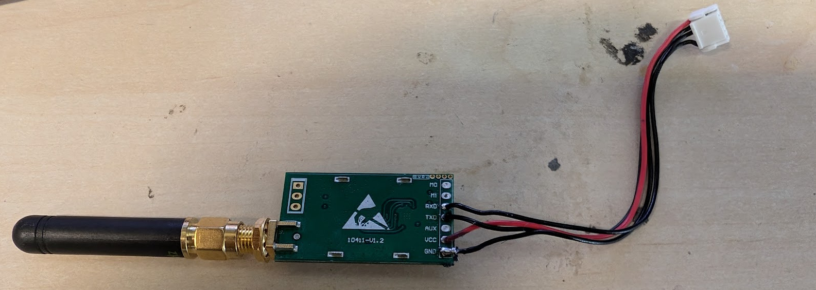
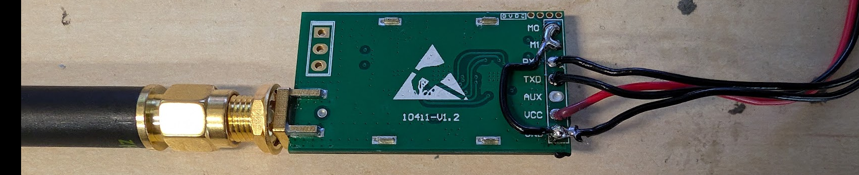
The LoRa module M0 and M1 pins should be pulled to GND for normal operation (solder a wire to GND). In this state, the module cannot be configured via FTDI. To reconfigure, remove the pull-downs on M0 and M1, perform the configuration, then re-solder the pull-downs.
-
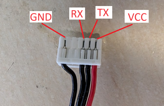
Solder a 6-pin JST-GH connector to the LoRa module (Pixhawk standard pinout):
-
Configure the LoRa module by connecting it to your PC via FTDI and running RF Settings.
Changing the channel changes the frequency — MRS drones use channel 13, Agile drones use channel 18.
Your configuration should look like this: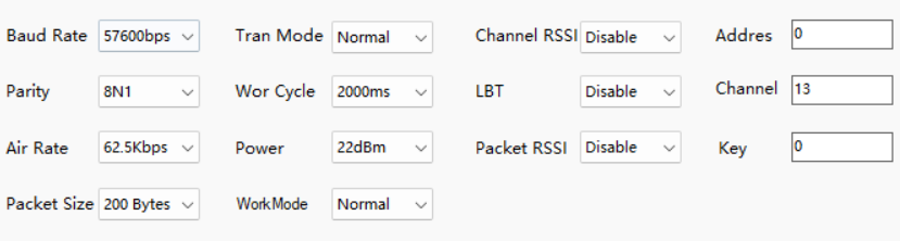
-
Short M0 and M1 to GND after configuration is complete:
F9P – Base Station & Drone
-
Configure the F9P in u-center. Select the correct COM port in the top-left and connect. Then go to Tools → Receiver Configuration… and load the appropriate config file depending on whether you are configuring the base station or the drone unit:
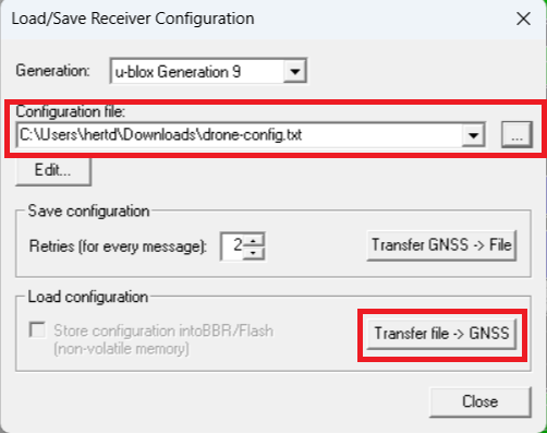
-
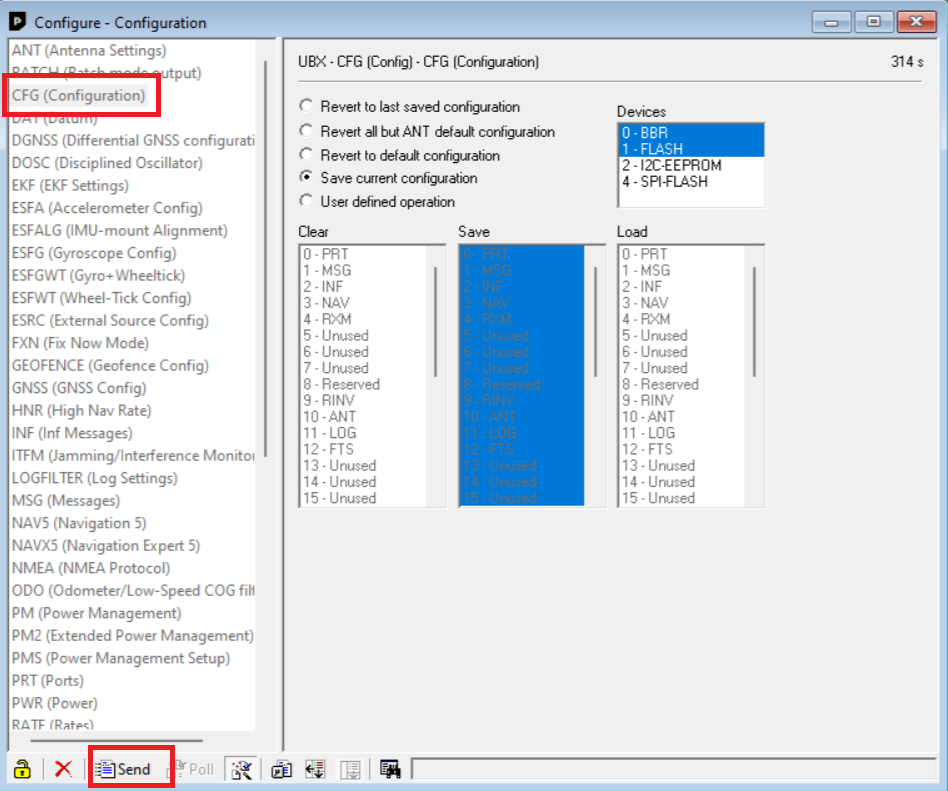
Save the configuration. Go to View → Configuration View, scroll to CFG (Configuration), and click Send:
Base Station Build
Parts to Prepare
- Tripod
- Base station antenna
- 3D-printed parts (print 1× each):
Alternatively, find the models in Fusion Hub under Sandbox → RTK → 3D Prints. A newer version may be available there.
- The bottom holder houses the Arduino and LoRa module, and snaps onto the tripod rod.
- The RTK base holder secures the RTK base station.
RTK Module
Insert M3 nuts into the RTK base holder, then use 3× M2.5×6 screws to secure the RTK base station to the part.
Arduino
Download and upload this sketch to the arduino nano.
After uploading the sketch, snap off the pin legs on the Arduino so it fits into the designated slot on the bottom holder. Secure it with zip ties through the small holes provided.
LoRa Module
The LoRa module mounts via its SMA connector on the bottom holder. Secure it with a low-profile gold-plated nut.
Cable Routing
| From | To |
|---|---|
| LoRa VCC | RTK UART2 5V |
| LoRa TX | RTK UART2 RX |
| LoRa RX | RTK UART2 TX |
| LoRa GND | RTK UART2 GND |
| Arduino 5V | RTK UART1 VCC |
| Arduino D3 (TX) | RTK UART1 RX |
| Arduino D4 (RX) | RTK UART1 TX |
| Arduino GND | RTK UART1 GND |
The bottom holder has zip tie slots to keep cables tidy.
Final Assembly
- Snap the bottom holder onto the tripod.
- Secure the RTK base holder to the bottom holder using 4× M3×20 screws.
- Connect all cables and attach the UFO antenna.
- Power the base station via plugging USB into the Arduino nano
Common Issues
-
Arduino ↔ RTK base station communication failure: Check the UART2 baud rate in u-center — it must match the value set in the
f9p.begin()call in the Arduino sketch. Typically57600. -
RTK base station not broadcasting corrections: The base station needs to meet a minimum observation time and position accuracy before it starts broadcasting. If it never starts, it likely hasn't crossed one or both thresholds. Adjust the
TIME(seconds) andACCURACY(meters) variables in the Arduino sketch.