This page is for everybody who wants to use the Series 1585 Thrust Stand by TYTO ROBOTICS. The stand is able to measure following parameters:
- Thrust [kgf] [-5 to 5]
- Torque [Nm] [-2 to 2]
- Voltage [V] [0 to 50] and Current [A] [0 to 55]
- Rotations Per Minute [RPM] [0 to 100k]
- Motor winding resistance [Ohm] [0.003 to 240]
More details are can be found in the device datasheet here.
For people who already used the device in the past a quick checklist can be found at the end of the page to perform experiments without going through the whole manual in detail. Remember that all safety precautions should be complied.
🔴 Update: We now have an expansion board allowing us to natively use the DShot protocol we are running on our drones. Also the control box is now not needed to operate the thrust stand.
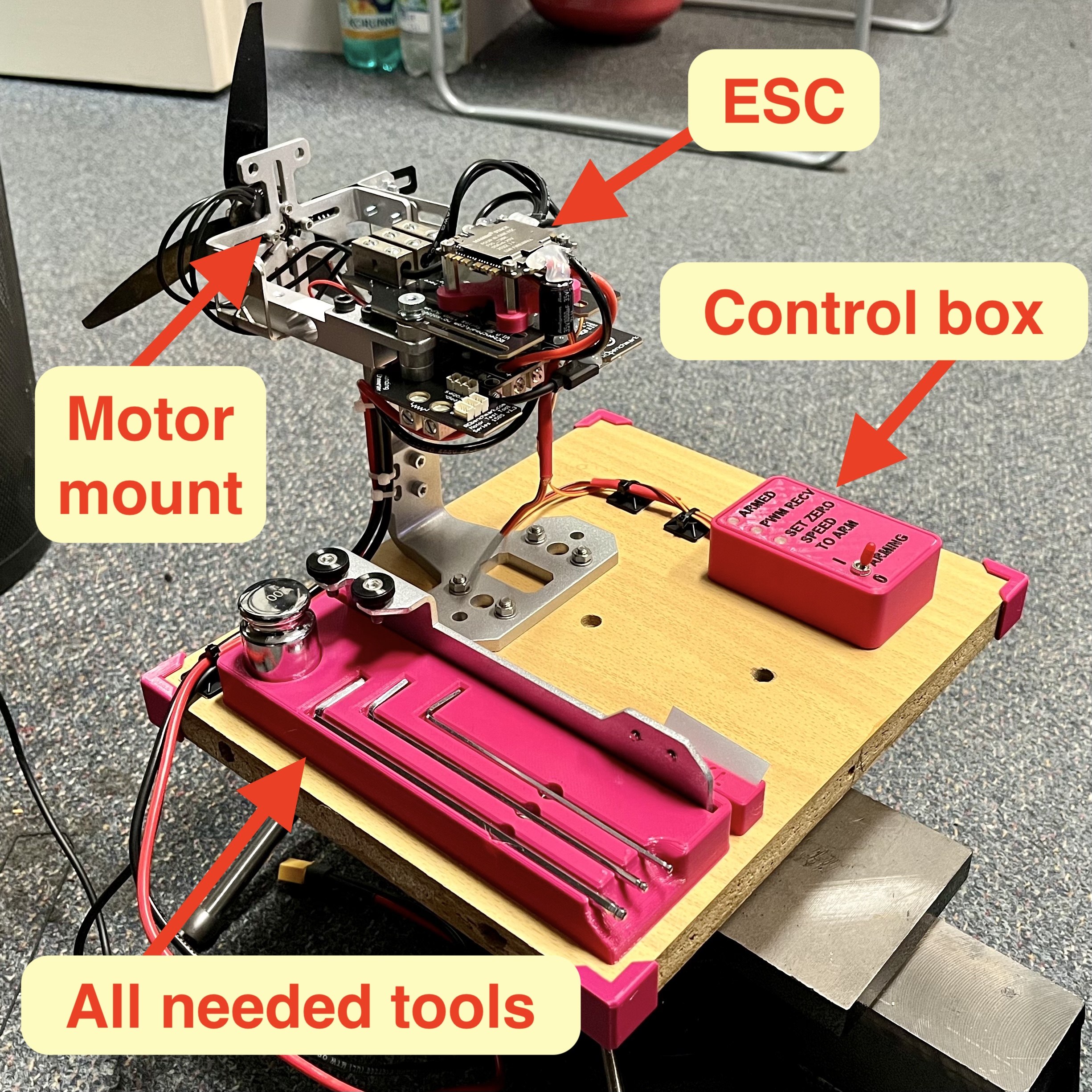
General overview
The device contains everything needed to use it except the motor and propeller. That has to be mounted by you.
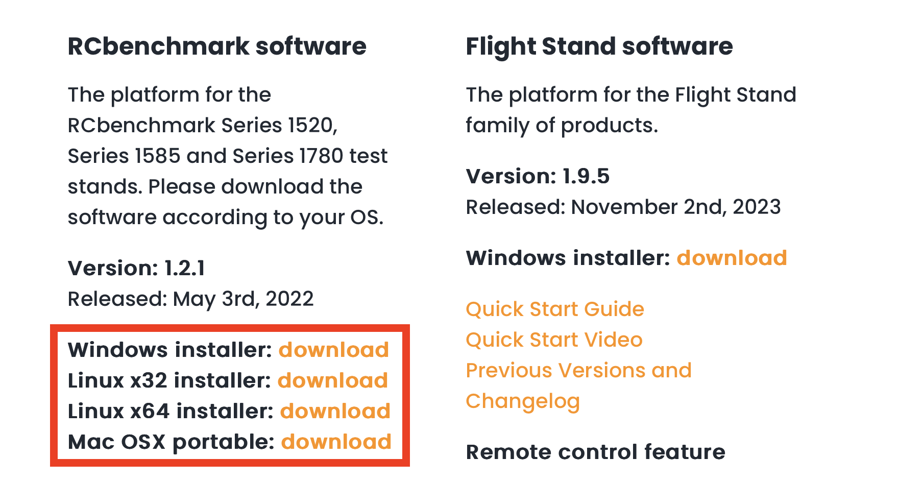
Required Software
The software required for this is the RCbenchmark app (download link here) available for Windows, Linux (64 and 32 bit variants) and Mac OS X. Please install it before powering the device for the first time.
How to prepare an experiment
The following text will guide you through everything needed to prepare and set up before running an experiment with a propeller.
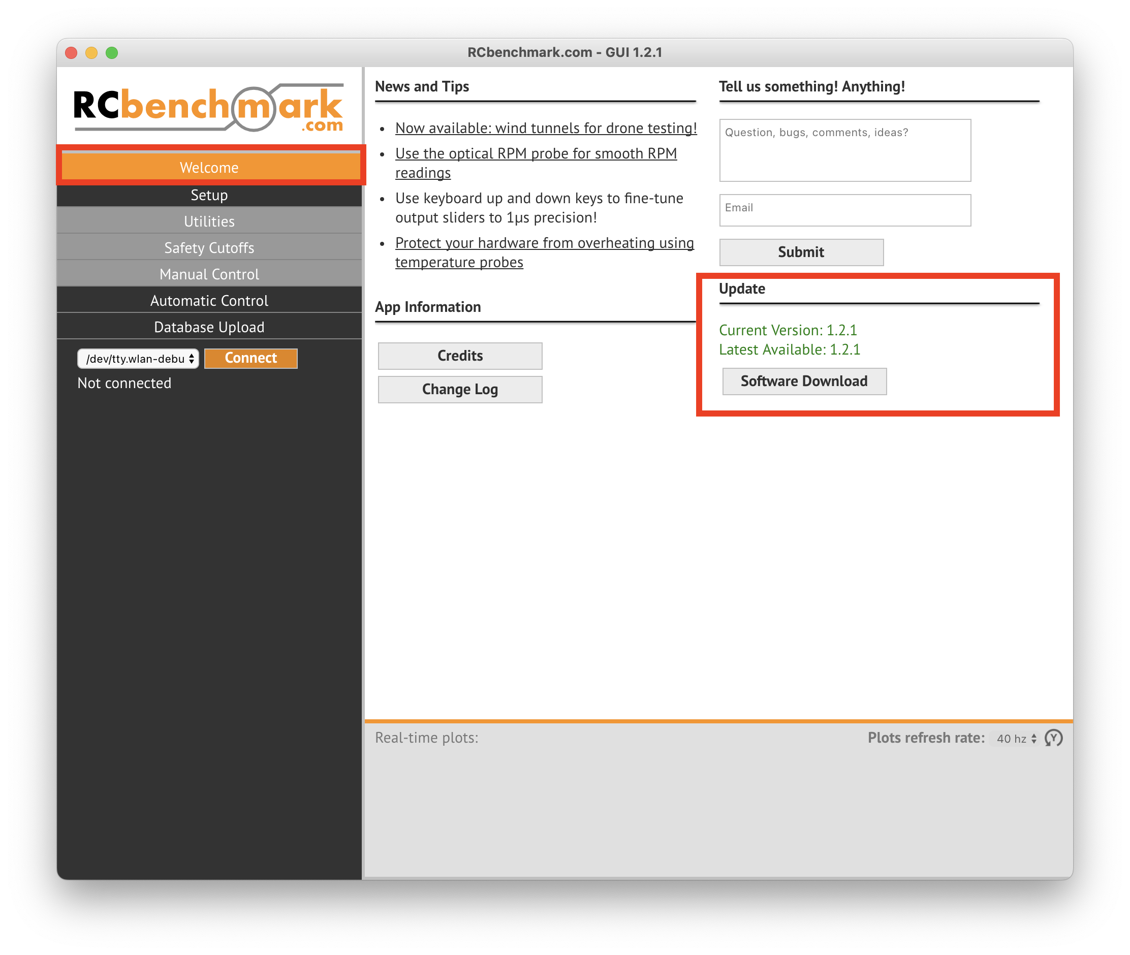
1. Software setup
Download and install the RCbenchmark app (download link here). After opening the app check that you are running the latest version in the Update section on the Welcome page.
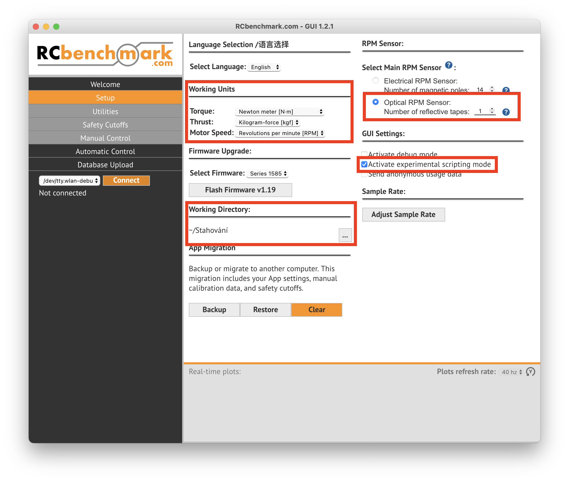
Then go through the setup page and set your Working units and choose your working directory (mandatory for automated motor testing logs). Select the main RPM sensor to be the optical one (if you plan to install it - see below). This ensures higher RPM reading precision.
If the optical sensor is not going to be installed, then fill in the magnetic pole count of your specific motor.
To get this number follow the guide under the ? mark.
To use the automated testing feature, tick the “Activate experimental scripting mode” option.
DO NOT CONNECT THE BATTERY NOR POWER SUPPLY TO THE XT-60 CONNECTOR AND CHECK THAT THERE IS NO PROPELLER INSTALLED ON THE MOTOR!
Connect the thrust tester to your computer via the included USB cable.
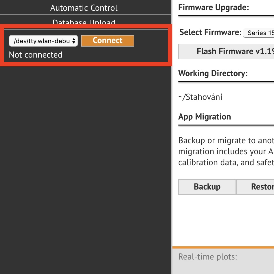
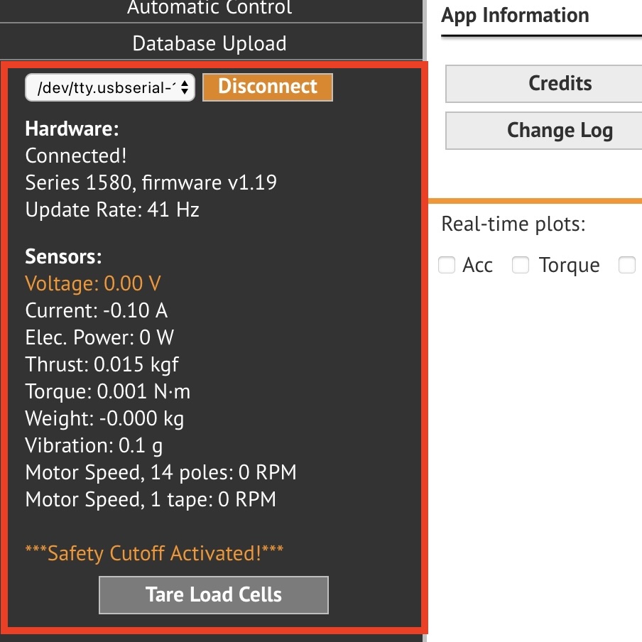
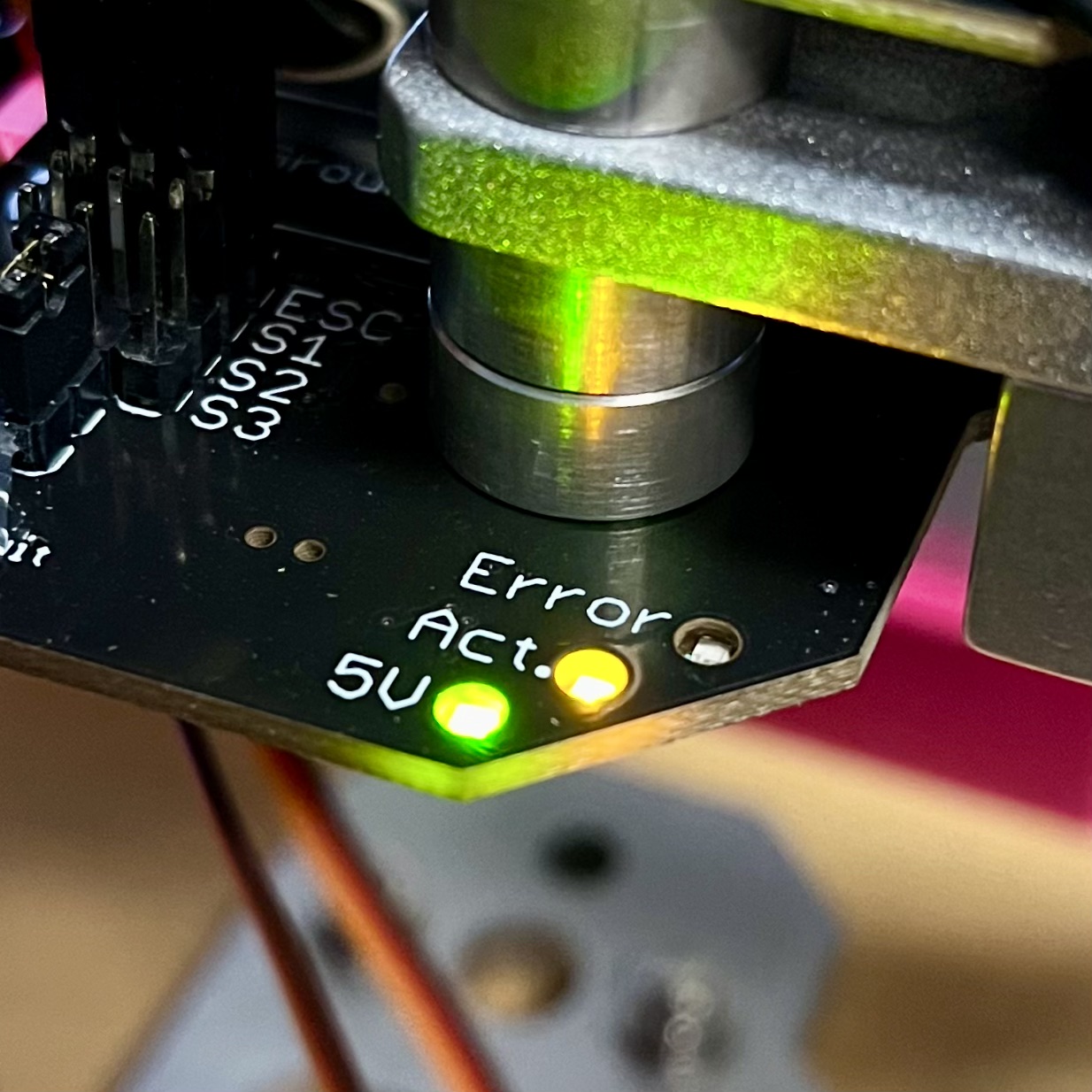
On the left side, locate the appropriate serial port and hit connect. After successful connection you should be able to see realtime values coming from the device. Furthermore the “Act” LED should be quickly blinking on the device.
You can also check if there is a new firmware version for Series 1585 thrust tester (v1.19 is currently flashed - last update: 22.12.2023).
Now set all of the safety cutoffs in the Safety Cutoffs tab on the left. The testbed will automatically cut power to the motor if the set values are exceeded. Note that the values are dependent on used hardware but the most important are minimum voltage and maximum current.
If the MAMBA STACK ESC is installed, then set the "max. Continuous Current" to 50 A and "max. Burst Current" to 60 A. For "min. Voltage" set 13.6 V for a 4S battery and 20.4 V for a 6S battery.

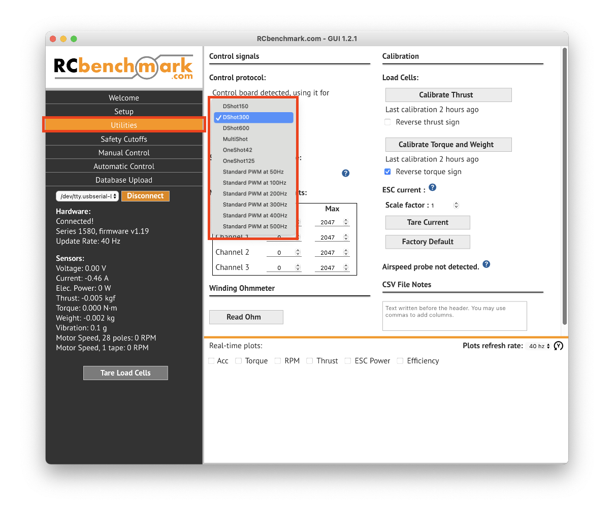
Last step should be setting the ESC protocol. The setting is called "Control protocol" and can be found in the "Utilities" menu. In MRS we almost always use the DShot300 protocol. It should also be set for teh provided MAMBA STACK ESC. If You are using your own ESC feel free to set the "Control protocol" to any value needed.
2. Thrust calibration
The device sensors have to be calibrated before each experiment!
For this test the device should be vertically mounted and no motor should be installed. If you have the motor on from previous experiments don't be lazy and take it off for the calibration process.
Now go to the "Utilities" tab, hit the “Calibrate thrust” button and follow the provided manual.
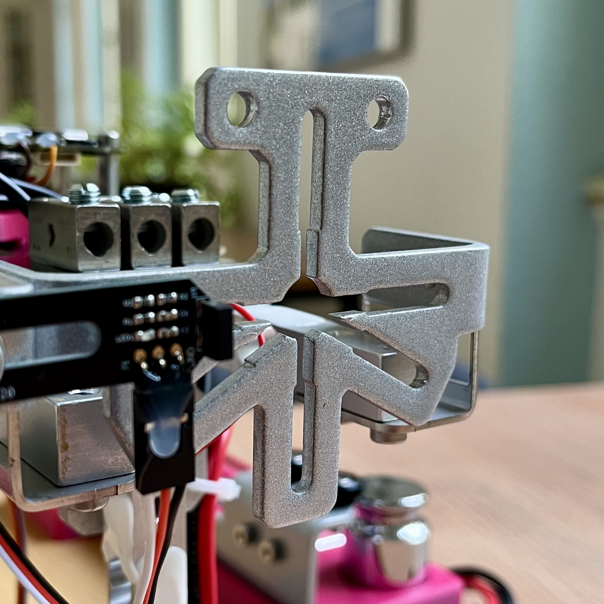
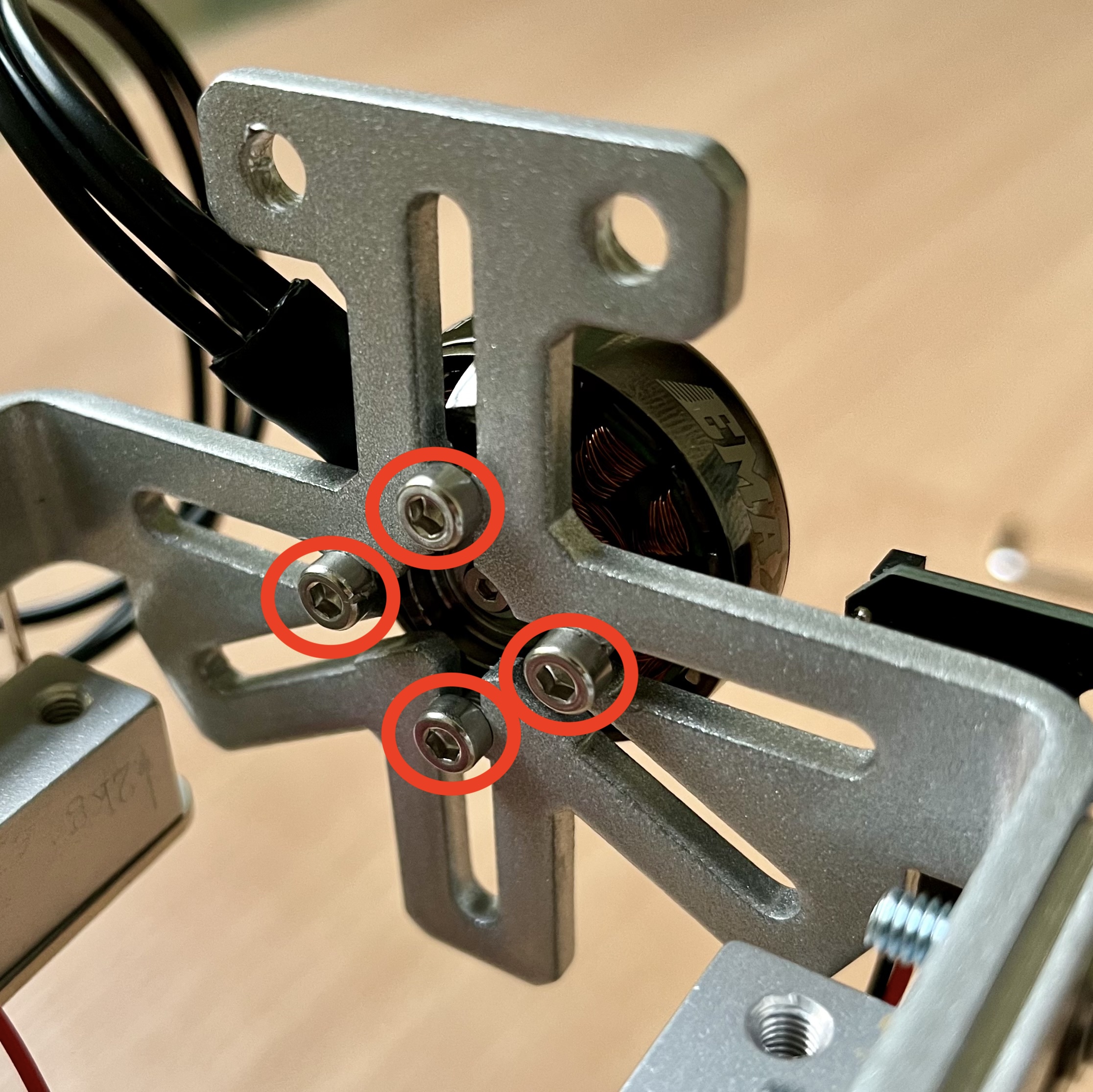
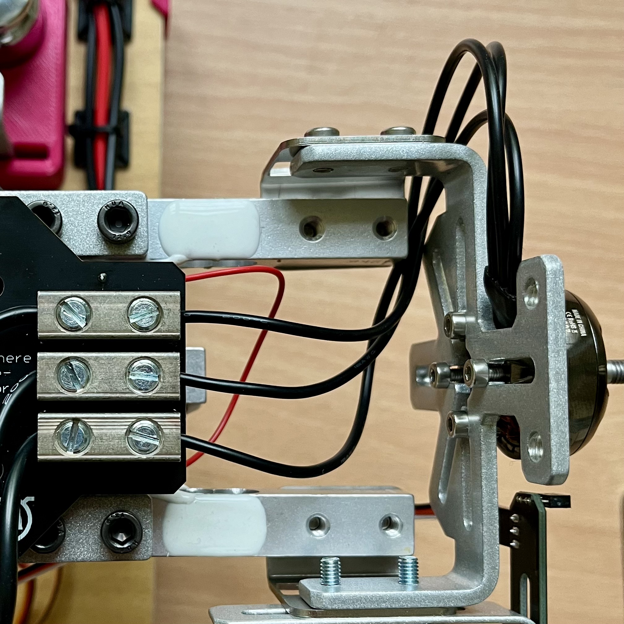
3. Mount your motor to the thrust tester
Use the universal mounting plate located at the front of the device. Note that bolts of proper size and length should be used for the motor mounting. Also at every circumstance ALL FOUR BOLTS HAVE TO BE USED to ensure proper safety under operation.
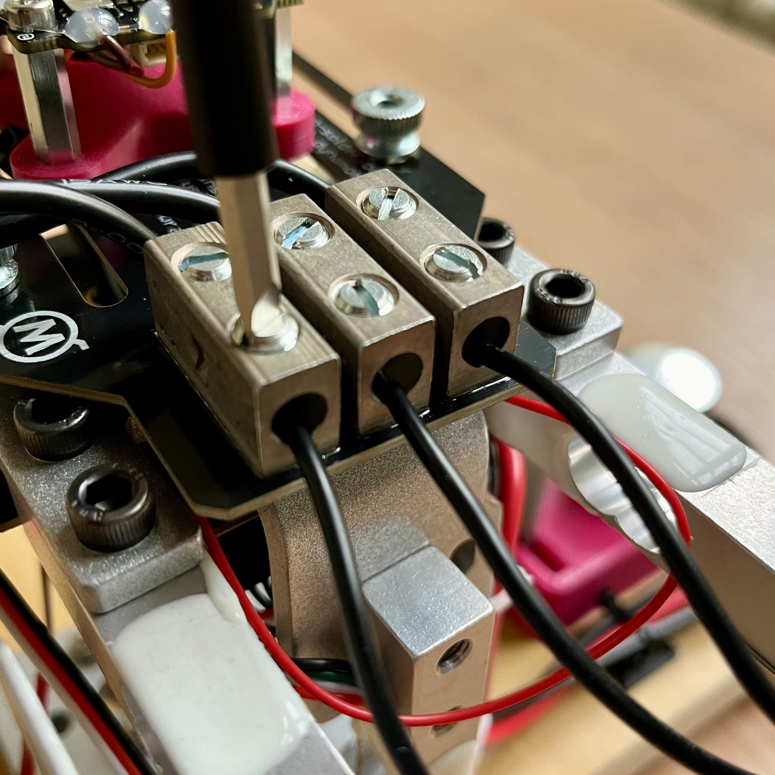
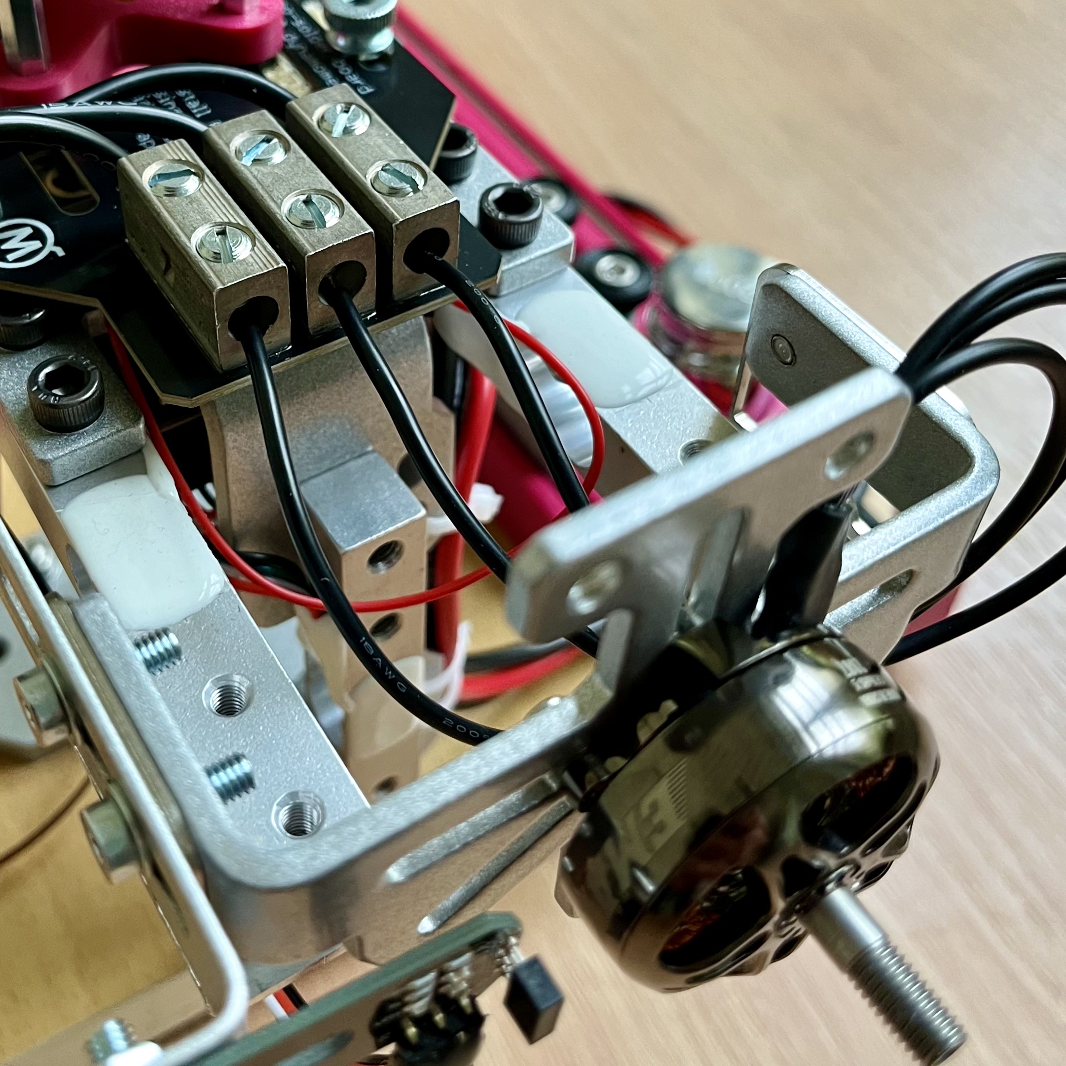
Now connect the three motor wires to the nearby terminals. The order does not matter but ensure that the wire is not pinched anywhere and has enough slack so it does not pull on the motor. The terminal screws should be tight but do not overdo it. DO NOT INSTALL THE PROPELLER YET!
4. Optical RPM Measurement (Optional but recommended)
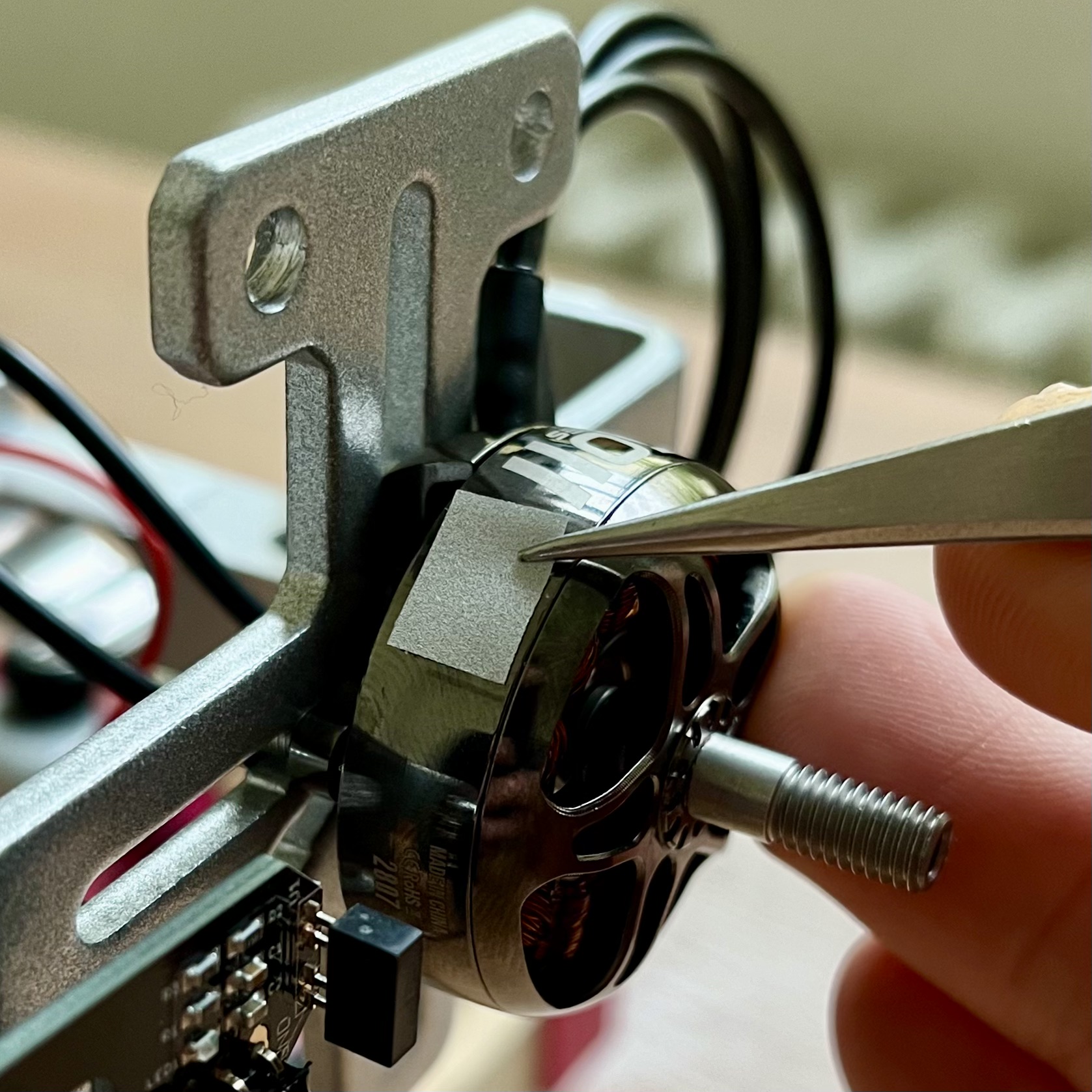
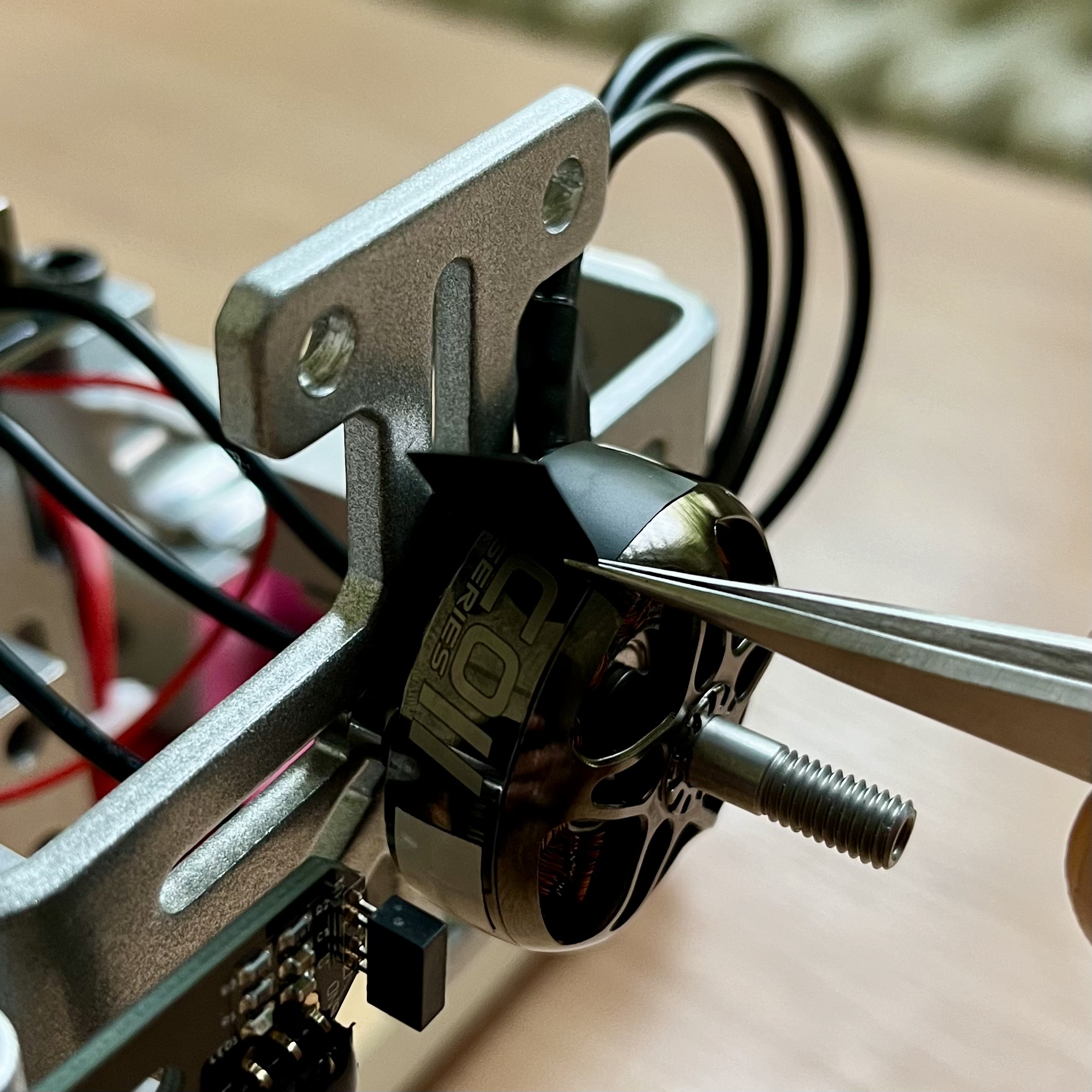
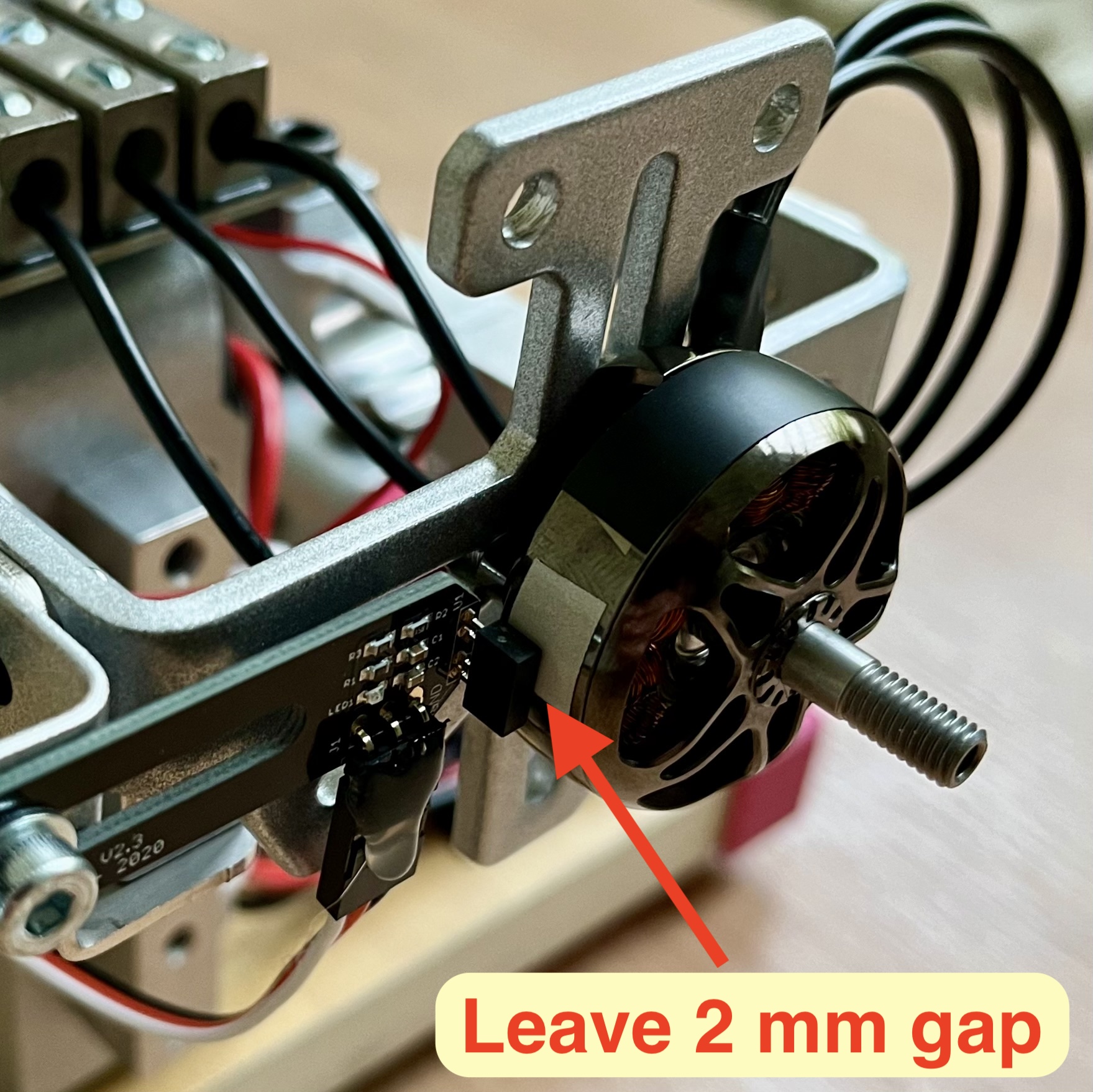
If exact RPM reading is required use an optical RPM sensor. In order to use it you have to put a reflective sticker on the motor (it can be found in a 3D printed case on the testbed) and cover all reflective parts of the motor housing with a black electrical tape as shown.
Sometimes letters on the motor housing or the housing itself can be reflective so it may be needed to cover the whole circumference of the motor in black tape and add the reflective sticker after that.
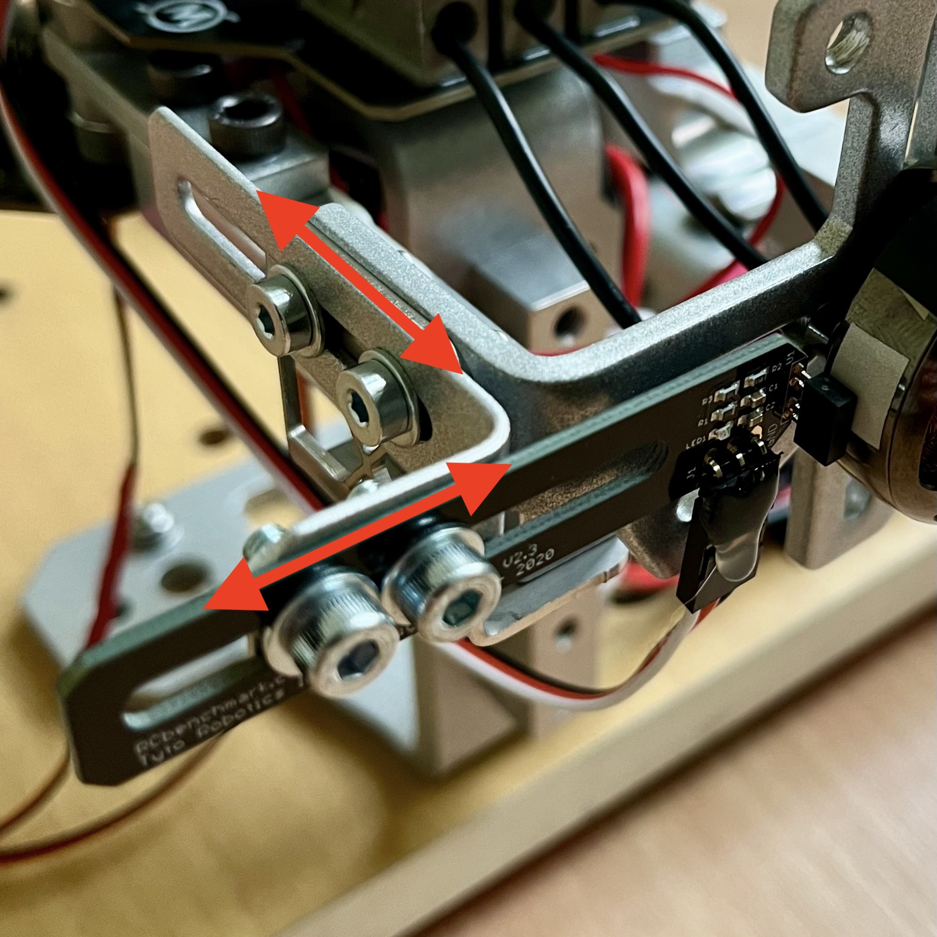
Next the RPM sensor position has to be set perpendicular to the motor and ideally 1 to 2 mm far from the motor housing i.e. the sticker. To adjust the sensor use the provided allen keys. Make sure that all of the manipulated bolts are tight and the sensor cannot be moved by hand. Also try to spin the motor by hand and see if it is still spinning freely.
5. Calibrate Torque
The device sensors have to be calibrated before each experiment!
Go to the "Utilities" tab and run the calibration in the following order:
- Mount the whole testbed securely to the spot where you plan to use it. Please make sure that the mounting is safe to operate.
- Run the “Calibrate Torque and Weight” procedure and follow the provided manual.
- Now try to pull on the motor in the direction of thrust and observe the thrust reading on the left side of the window. If it is of incorrect sign, check the “Reverse thrust sign” checkbox in the "Calibration" pane.
6. Mount the propeller
THIS SHOULD ALWAYS BE DONE WITH BATTERY AND POWER SUPPLY DISCONNECTED!
Mount the propeller to the motor and make sure it is well secured and that the mounting bolts are not too long to interfere with the motors windings. Now try to spin the propeller by hand and make sure it is not colliding with anything and can spin freely. At this time you can also check that the optical RPM sensor is working as it should (“Motor Speed” reading on the left side of the window).
7. Final check and battery connection
Make sure everything is safely mounted and connect the battery or power supply through the provided XT-60 connector.
After connecting the battery (or power supply) hit the “Tare Current” in the "Utilities" tab and the “Tare Load Cells” button on the left side of the app window.
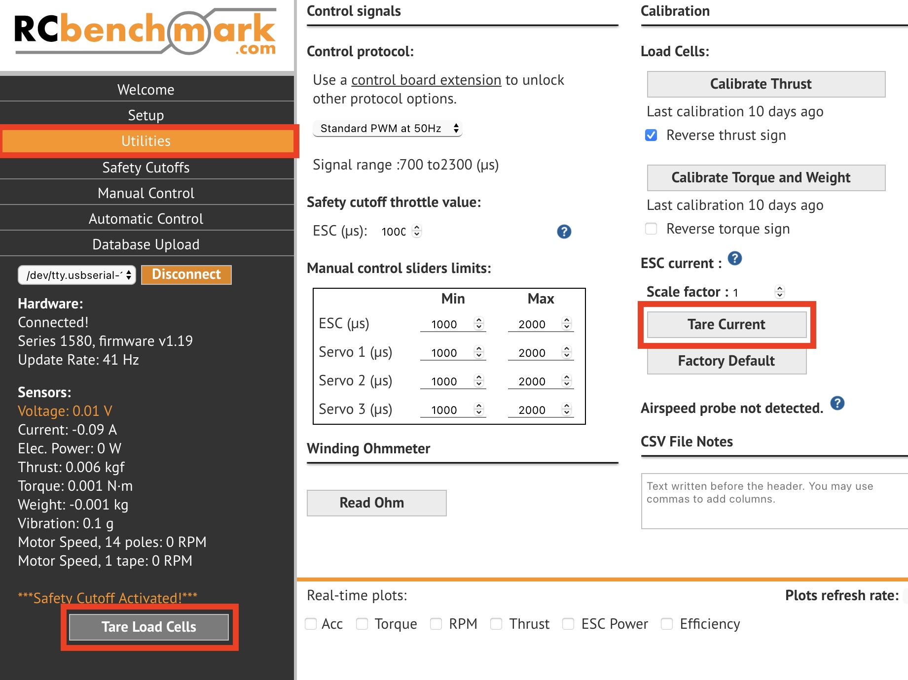
Look at the realtime values (left side of the window) and you should see correct battery Voltage (14.8 to 16.8 V for a 4S and 22.2 to 25.2 V for a 6S battery), zero Current, zero Thrust, zero Torque and zero Weight. If not, disconnect the battery and run all of the calibration steps again. If this does not help, then ask for help in the hardware room.
8. Manual test
Now the setup should be tested manually before running any automated tests.
Ensure maximum safety while running the motor with the propeller. Eye protection is recommended.
Go to the “Manual Control” tab and check the box under ESC. Make sure that the slider is all the way down and that the number below is showing 1000. The motor should now perform a beeping sound.
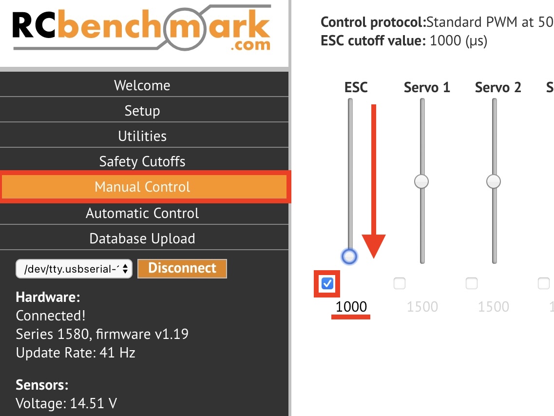
Step back and try to adjust the throttle (“ESC”) slider in the app. The motor should be spinning.
If You are planning to do any automated tests, then try if the motor is behaving safely and correctly in the whole throttle range that you plan to later test with!
Remember that the “ESC” slider should be in the “0” position and it's checkbox should be unticked at every time except the active experiment so do not forget to switch it back after the manual test.
Running an experiment
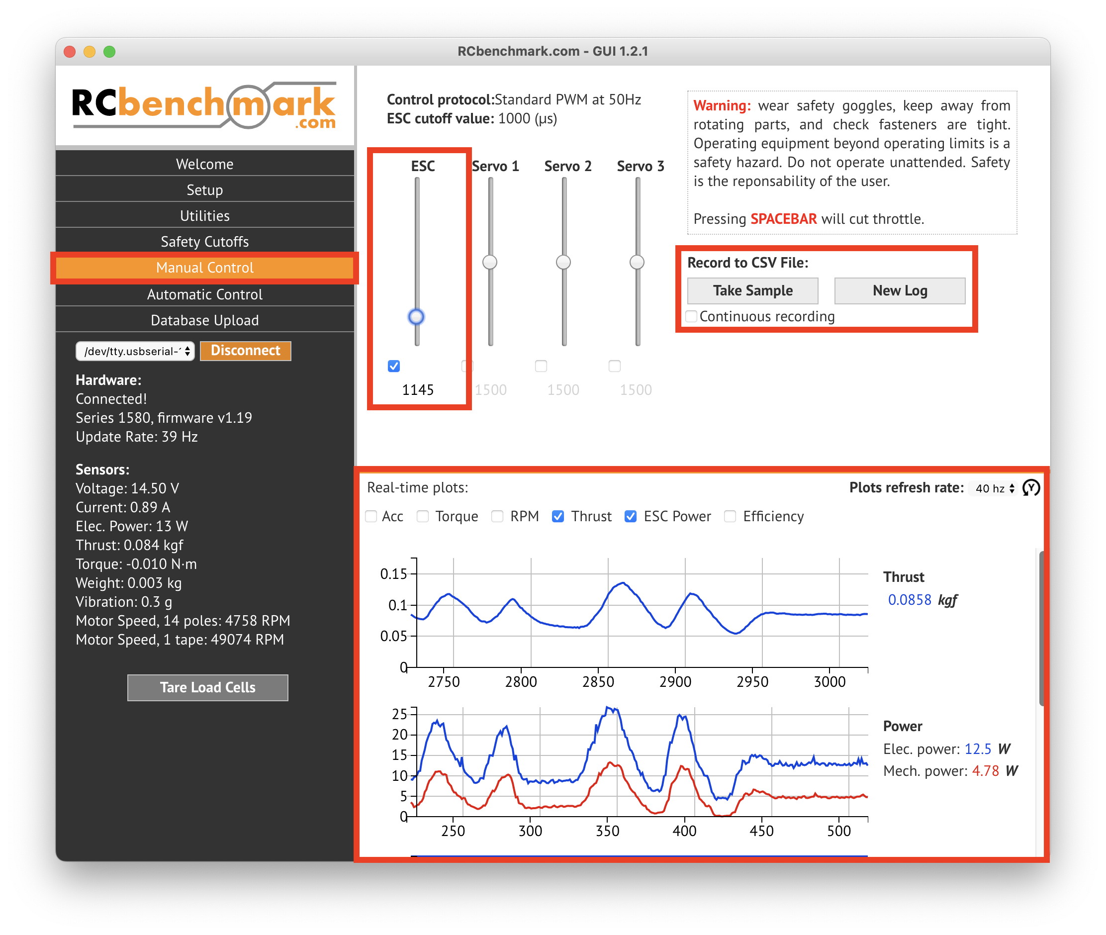
If manual control is enough for your test you can then set it up the same way as in the previous steps and record the values either from the real time plots in the app (see picture below) or save them into a ".CSV" file. The file will be created in the Working Directory set in the "Setup" tab before.
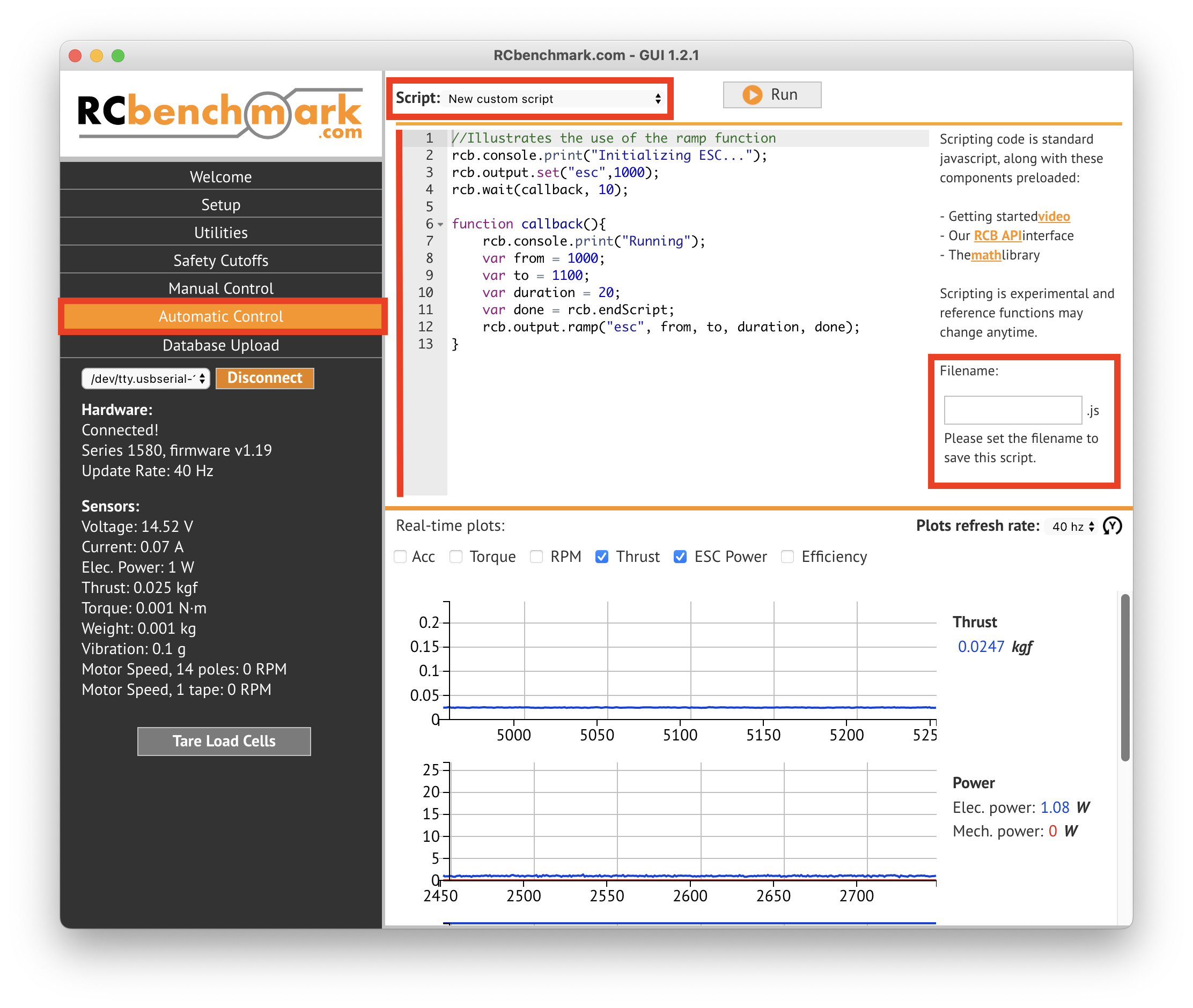
For automated testing go to the “Automatic Control” tab on the left. Testing scripts can be written in RCbenchamrk floavoured javascript directly in the app. The file can be saved to your computer by giving it a name on the right side of the window. The file will be then saved to the Working Directory set in the "Setup" tab before.
Help for the scripting can be found under the links on the right side of the app window. Or in the official RCbenchmark getting started video and in the RCB API documentation.
Quick experiment checklist
This checklist is not for newcomers. It should serve people who have already gone through the whole manual before and want to safely setup an experiment again without reading the whole thing. The checklist is missing detailed safety check information so make sure that the experiment will run smoothly by yourself.
- Everything is disconnected and powered off
- Plug the device into computer and connect it to the app
- Check app and firmware version and get the latest of both (the device is Series 1585)
- Go through the Setup tab
- Calibrate Thrust (Utilities tab)
- Mount the motor with no propeller on and optionally set the RPM sensor (don't forget the stickers)
- Mount the device securely to a table
- Calibrate Torque in the Utilities tab
- Mount propeller and check if it spins freely
- Connect battery or power supply
- Try a manual test
- Do any testing you want