All part list
- Electro
- Distribution board (custom PCB)
- GPS kit - M9N
- Flight Computer Unit (FCU) - Kakute H7
- Electronics Speed Controller (ESC)
- Receiver - Happymodel ELRS 2.4G EP2 TCXO
- XT60 with nuts
- Raspberry Pi 5
- Raspberry cooling kit
- 4x motor kits
- RGB camera
- other camera
- Extra camera lens
- 150mm ribbon camera cable
- Hardware
-
CF Center board (2mm thick)
-
CF Base board (4mm thick)
-
XT60_cover.stl - 1x (black PETG)
-
XT60_cover+back-cam-holder.stl - 1x (black PETG)
-
UWB_holder.stl - 1x (black PETG)
-
Back-cam-cable-cover.stl - 1x (black PETG)
-
Rpi_cover.stl - 1x (black PETG)
-
FortiLeg.stl - 4x (2x black PETG, 2x red PETG)
-
BatterySupport.stl - 2x (black PETG)
-
HatSpacerCut.stl - for version with AI Hat
-
Part preparation
What you need:
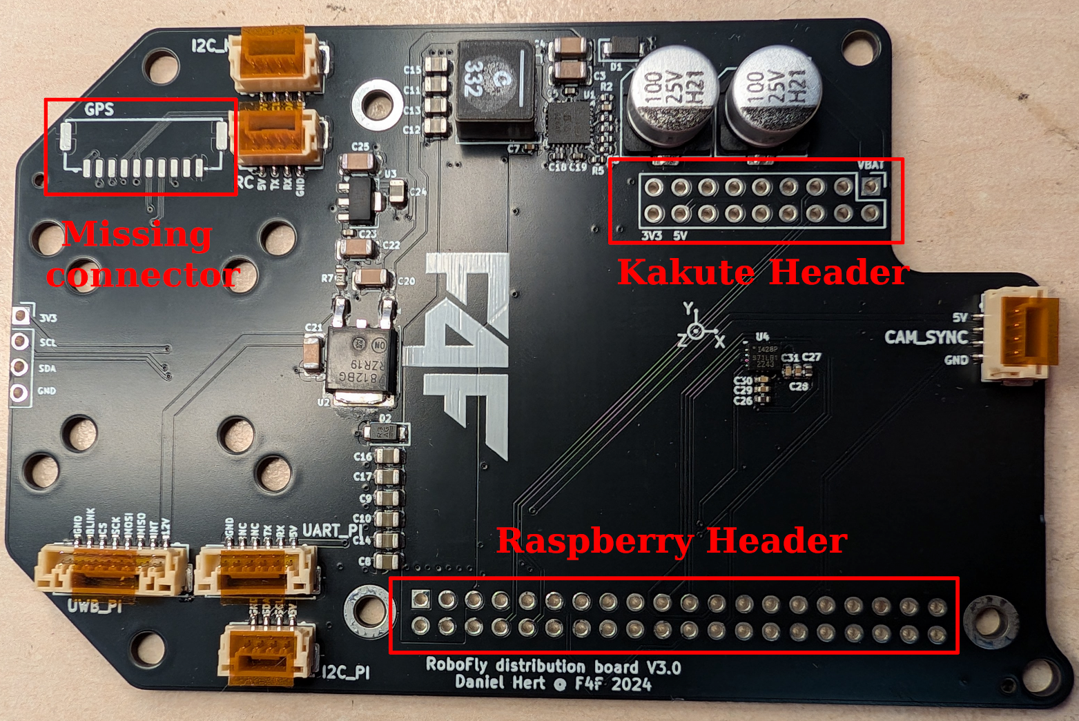
- Distribution board which might be only partially populated
- Any missing parts from the distribution board, usually JST-GH connectors
- 1x Stacking header for Raspberry Pi
- 1x male header for Kakute H7 (2x9 pin)
- 1x female header for Kakute H7 (2x9 pin)
- Happymodel ELRS 2.4G
- 4-pin JST-GH cable (from an old Pixhawk)
Distribution board
-
Solder any missing parts to the distribution board, usually JST-GH
-
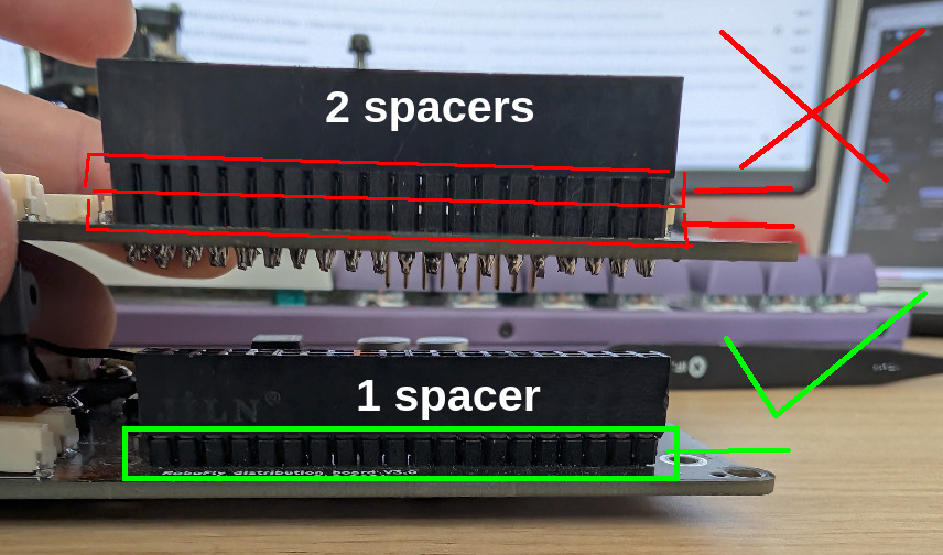
The stacking header for Raspberry pi can come with several spacers. We need exactly one spacer to be installed:
-
Solder the stacking raspberry pi header to the board. Use 14 mm M2.5 standoffs to mount the Raspberry Pi to help with alignment. After soldering, clip off excess legs:
-
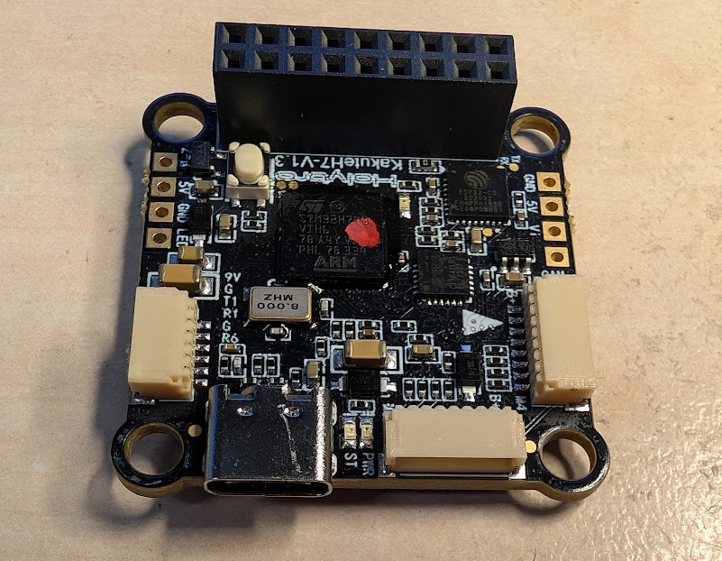
Solder the Female header to Kakute H7 in this orientation:
-
Now we have to solder the male header to the distribution board. NOTE: the header is soldered in a very counter-intuitive way, so pay attention 😄 )
-
Insert the header in this orientation:
-
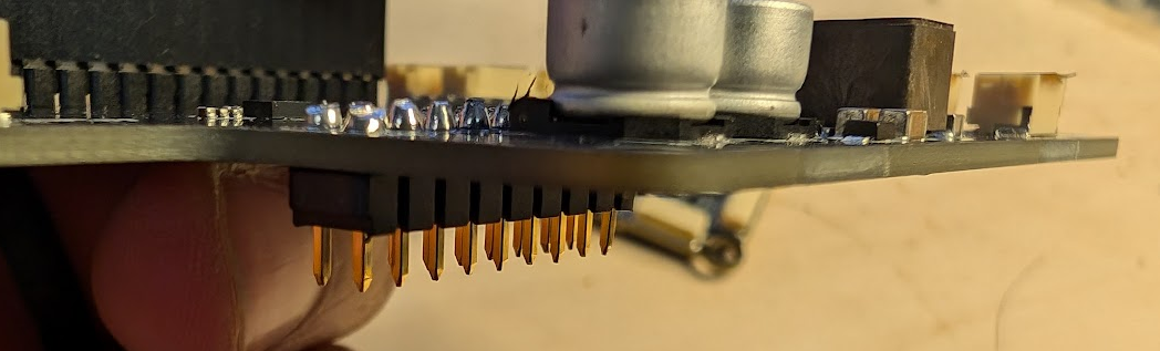
Solder the pins from the top. You can solder the first row, then cut off the excess with cutter so that you can access the second row easier (the caps are in the way). Once soldered, cut off the excess pins
-
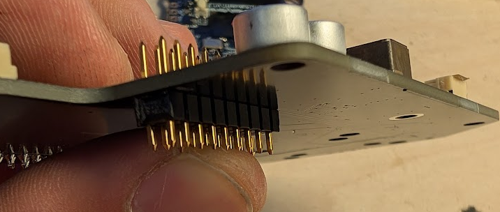
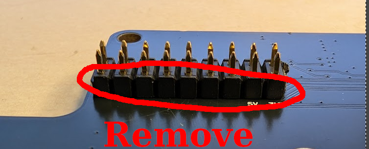
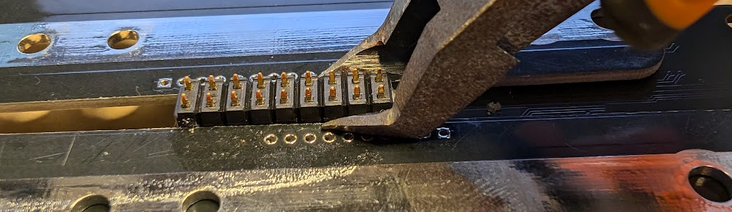
Now the hard part, we have to remove the black plastic piece holding the pins together, without bending the pins or scratching the board.
-
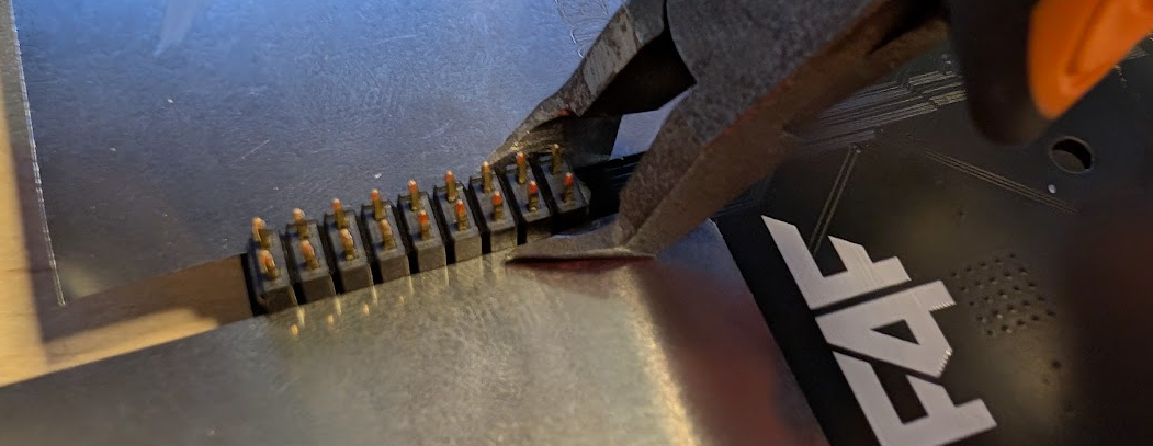
To do this, you will need special pair of cutters, some old PCBs and old pieces of SMD Stencils.
-
Put the stencils around the black plastic spacer, and gentely press with the cutters. This will lift the plastic up. Do not push too hard, or you will cut off the pins.
-
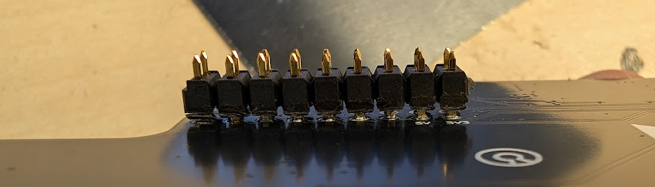
Once you run out of clearance, replace the stencil pieces with old PCBs (they are taller). Repeat the process. This should be enough to remove the plastic part.
-
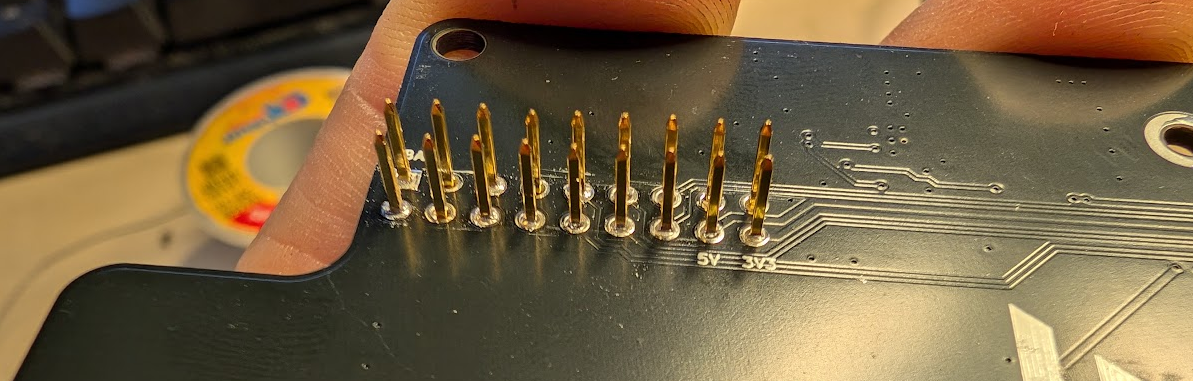
The pins should be straight. Make sure that they are all properly soldered in and not moving. If you need to resolder a pin, use the Kakute Female header for alignment.
-


RC
-
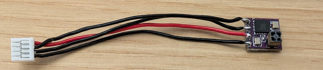
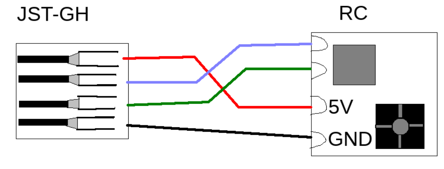
Solder a 4-pin JST-GH cable to the RC like this:
3D prints
Print the following items:
XT60_cover.stl - 1x (black PETG) - insert M3 threaded inserts, 2 pcs
Rpi_cover.stl - 1x (black PETG)
FortiLeg.stl - 4x (2x black PETG, 2x red PETG)
BatterySupport.stl - 2x (black PETG) - insert M3 threaded inserts, 2 pcs per support
Here is whole bundle for that:
Kakute H7 SW setup
You need to first setup the Kakute FCU with the PX4 firmware, as it comes with Betaflight from the manufacturer. Follow the guide here - https://mrs.fel.cvut.cz/wiki/articles/RoboFly/articles/RoboFly/Kakute-H7-SW-setup.md
Kakute H7 SD card config
Use the config from mrs_uav_deployment: https://github.com/ctu-mrs/mrs_uav_deployment/tree/master/miscellaneous/pixhawk_sdcard_config/kakuteH7/etc
Assembly
All mountings that should be secured with locktite will be labeled blue. Only use blue medium strength locktite
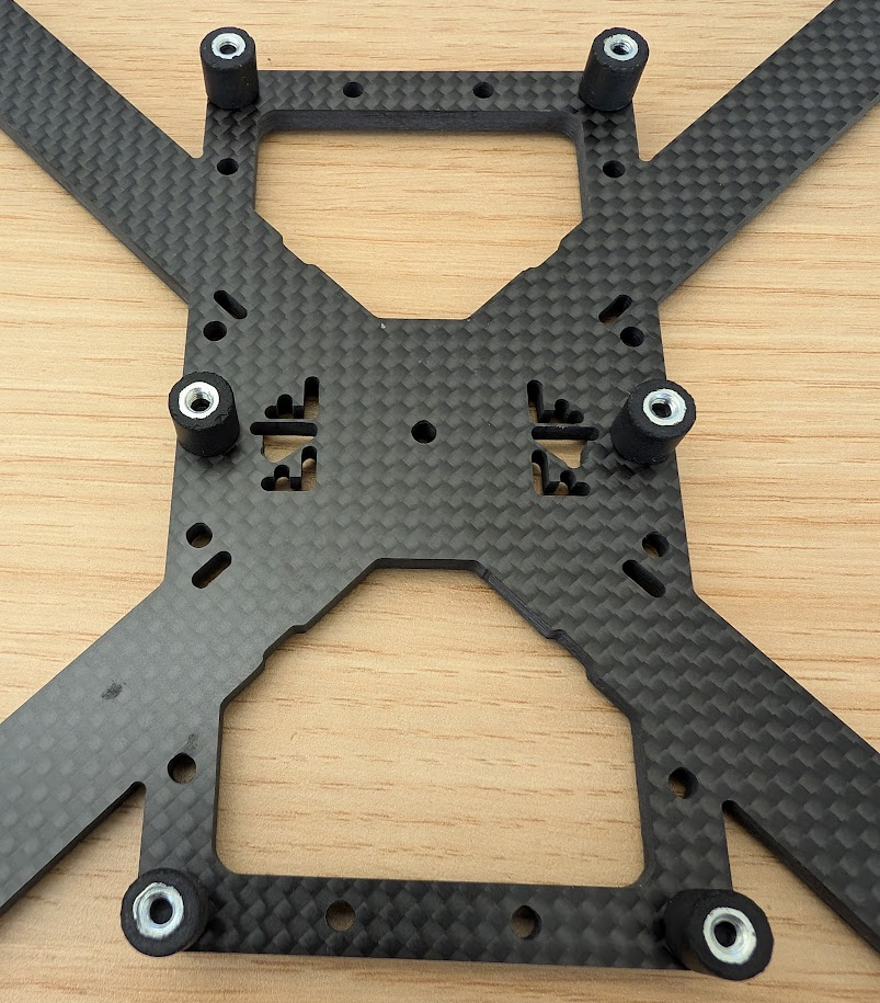
Frame
The frame consists of two parts, the lower board with motor mounts is 4 mm thick, the upper board for electronics mounting is 2 mm thick. Pay attention to the orientation of the boards. The lower board is symmetric in mechanical terms, but the cut out logos are not, so make sure they are aligned as shown in the picture.

Motors and legs
The motor cables are just long enough for our needs, so do not make them any shorter! The cables have to be sleeved with a braided sleeve, this is mostly for good looks, so pay attention to details. You will need black braided cable sleeve and some black heat shrink to secure it, these sizes work best:
-
Cut the braided sleeve 95-100mm long, type 6mm, 4 pieces
-
Cut the heatshrink 15-20 mm long, type 12mm, 8 pieces
-
Slide the braid over the motor cables, make sure that the cables are straight and parallel inside the sleeve, we do not want twisted cables inside!
-
Apply a tiny bit of hot-glue to the ends of the braids, once heatshrink is put over the ends and heated up, it will help with adhesion and make the assembly more resilient:
- Slide the heatshrinks over the ends of the braids and place them around 5mm in front of the motor, so theres some clearance for the motors to spin without hitting the sleeve.
- Then use a heat gun to shrink them
- Make sure to apply a bit more heat than usual, so that the hot glue melts and secures everything together.
The end result should look like this:
- Attach all 4 motors to the frame:
- Two different bolt lengths are used here
- 8x M3x8 (included) for attachment through the 3D printed legs
- 8x M3x6 for direct attachment of the motor
- Two different bolt lengths are used here
Attach like this and dont forget the thread locker
-
If you use the wrong bolt size, you can short out the motors!!!:
-
- Secure the cables with zip-ties as shown:
- The zip-tie was intended to go to the slot prepared for it, but this will make the cables too short to reach the ESC, so this is the solution for now. It will be fixed in next frame iteration (already fixed, use the milled slot for zip-ties)
- The zip-tie end should be on the top, not from the bottom of the board (for cleaner look)
- The zip-tie has to go over the braided sleeve with heatshrink, not just over the cables or braids! If the sleeve is too short or too long, you have to redo it:


Dampers
-
Attach 6x rubber dampers with 6x M3x6 bolts to the main frame and secure them with thread locker:
-
Note: due to the chaotic timeline of the making of this guide, some of the photos here will be out of order (like the photo above is missing its motors), or they will be of the older revisions. Please do not worry about this fact, just follow the guide :). Feel free to update the photos with better versions.
Center board
First of all, we need to solder a capacitor to the ESC and the header to the Flight controller
- Solder the cap from the bottom side of the ESC and angle it a bit back, like this:

- You should already have the FCU with the soldered header: (wrong image?)
- Mount the 3D printed Battery support under the ESC with 2x M3x4 bolts. Do not mount the second one yet
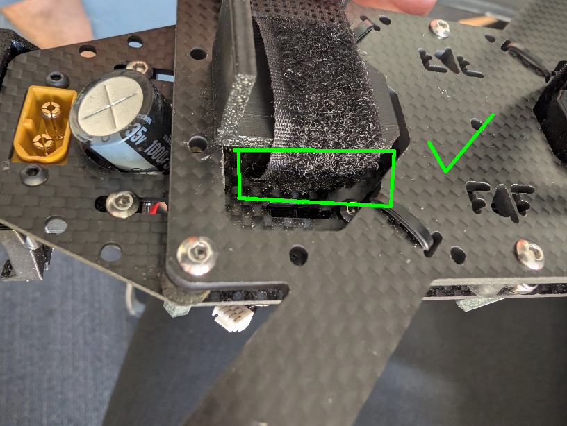
- Befor attaching the ESC, insert a Velcro strap to hold the battery. It has to go under the ESC:

- Mount the XT60 with M2.5 bolts.
- Mount both the FCU and ESC on the M3x5 standoffs using M3x4 bolts (even though ESC has holes for M4s). Note the polarity of the XT60 and the orientation of the FCU.
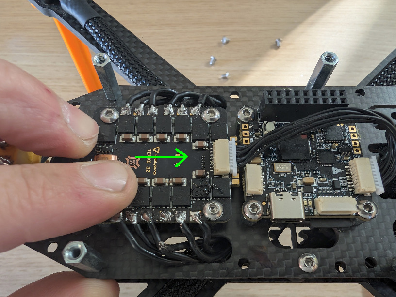
- The ESC can slide backwards and forwards, to compensate for motor cable length and different ESC types in the future. For the current setup, putting it all the way to the front works best. Do not tighten the ESC yet, you might need to adjust it.

-
Add 2 standoffs for the distribution board, they are 15mm M3 M-F. secure them with 2x M3 locknuts
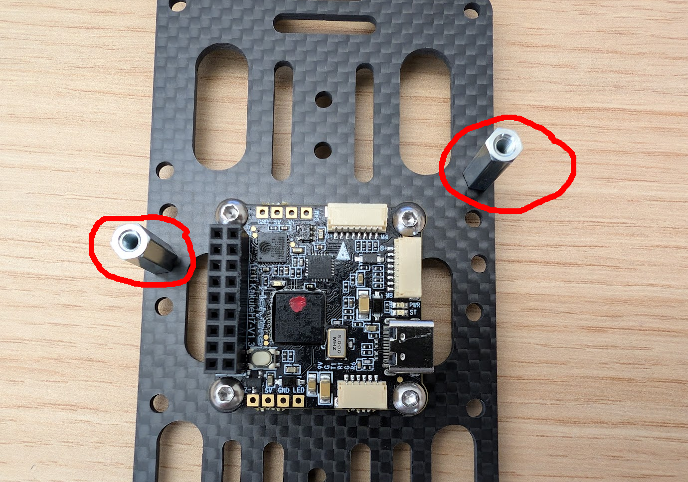
-
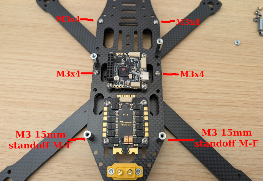
Assemble the electronics board and the board with motors. You might need to bend the capacitor a little or move the ESC back a bit to fit the board through. Pull the motor cables through the holes as shown in the image. Secure the board with 4x M3x4 in the front and middle and 2x 15 mm M3 M-F standoffs in the back. Secure all the threads with threadlocker:
-
Solder the motor cables to the ESC. Move the ESC forward, so that there is roughly a 1mm gap between the ESC and the FCU. This should give you enough slack to solder the motor cables properly.

- Solder wires from the XT60 to the ESC. Plug a male XT60 into the connector first, so that you do not move the contacts when heated up by the soldering. Use 10 or 12 AWG cables:

-
You should already have setup of the FCU ready.
-
Connect the cable from the ESC to the flight controller (not yet uder the FCU) and any 4S battery. Now you can try to spin the motors through QGroundControl. They will spin in the wrong order, which we will need to fix. This is the order in which the motor will spin before the fix:

- New versions of PX4 should be capable of doing this in SW, but we are still at 1.13.2, so we have to switch around the cables in the ESC to FCU connector.
- This is the cable pinout, you essentially just need to move all the motor cables by 1 spot:

- Test that the motors are now connected in the right order.
- We will also need to fix the motor spin direction now. Use BLheli32 FW for that as we need to set up the ESC firmware anyway. You need to make or borrow Dan Hert’s ESC programmer (you can make it from the spare ESC cable):

- Flash the ESCs to the newest firmware version, apply the Robofly config from mrs_uav_deployment, and set the correct motor direction.
- Verify that the motors are now spinning in the right order and in the right direction.
- Once they are route the cable Over (not below) the FCU.
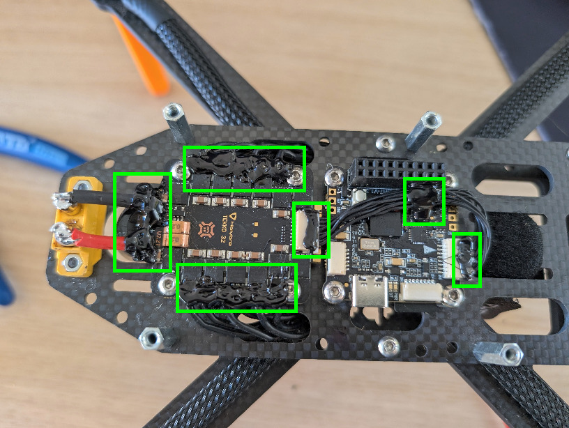
- Cover the motor cable solder points, ESC cable connections and power connections with Black hot glue. Also secure the FCU signal cable to the FCU. Do not worry about the XT60, that will be covered by a 3D print:
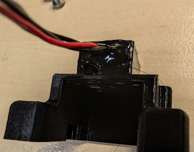
- Get the XT60 cover 3D print and the RC:
- Insert 2x M3 threaded inserts into the print
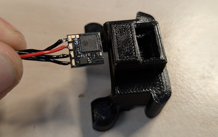
- Insert the RC into the 3D print, push it all the way back, with antenna facing downwards:
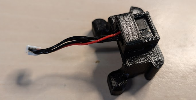
- Secure the RX with some black hot glue, like this:
- Attach the assembly to the frame (use thread locker) with 2xM3x4 bolts (Outdated picture, but you get the idea):
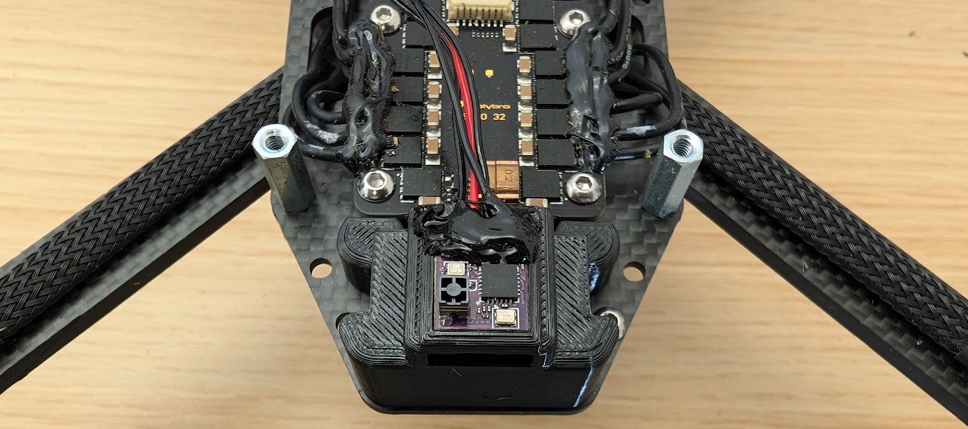
- Take the prepared distribution board, without the Raspberry Pi for now, and attach the GPS to it with 4xM3x8 (leftover from motors) and 4xM3 locknuts. Keep the nuts on the top, bolts from the bottom, to prevent shorts with the ESC.

-
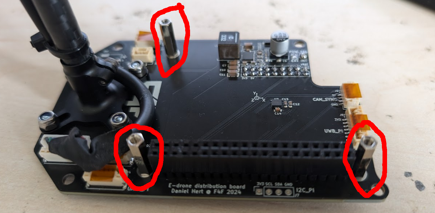
Attach 3x M2.5 14 mm standoffs for the Raspberry Pi. Secure them from the bottom with 3x M2.5 locknuts:
-
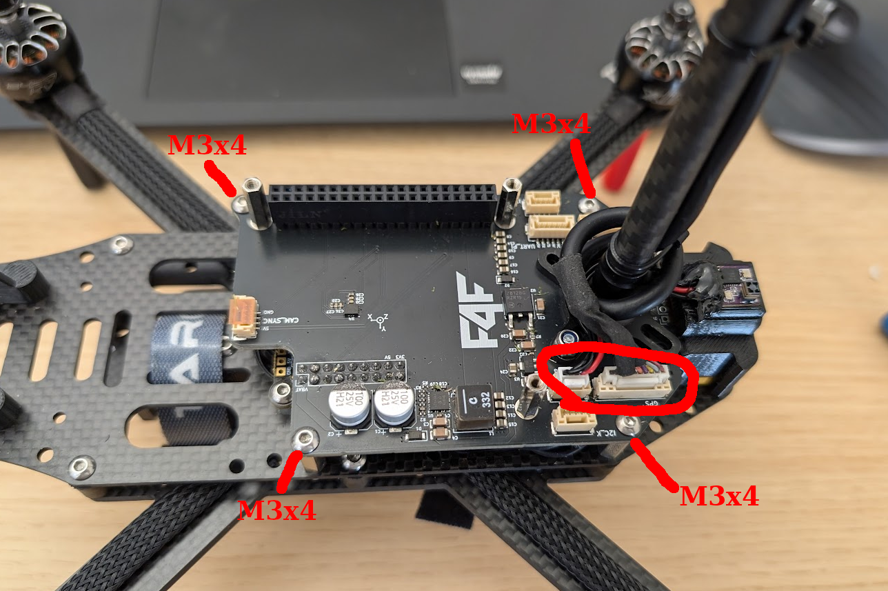
Attach the distribution board to the drone. Make sure to line up the Kakute header properly, so that you do not bend any pins. You can Make sure that the header is connected by all pins and that it is not offset. Connect the RC and GPS connectors. Secure the board with 4x M3x4 bolts:
-
Now add the second battery holder on the opposite side with M3x4 bolts.
-
Then route velctro fastener (dry zip) though these holes on the center board. PNG TBD
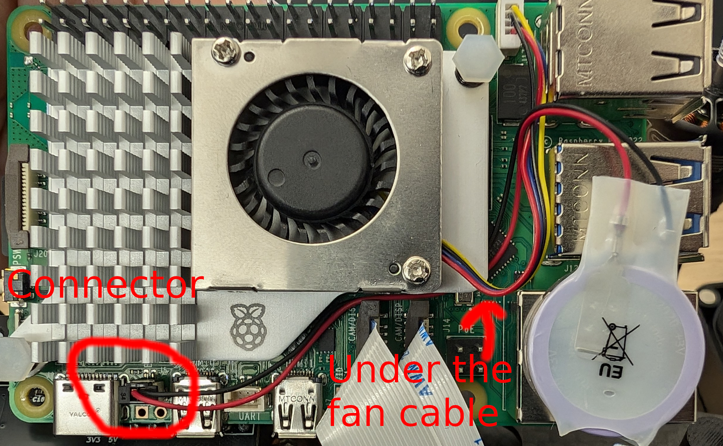
RTC battery install
The RTC battery is needed for the Rpi to keep time. The battery is rechargable, and needs to be a special chemistry ( ML-2020 Lithium Manganese Dioxide).
- Connect the battery to the RTC port, lead the cables under the fan cable, so that it does not flop about.
- Use the supplied adhesive pad to glue the battery to the ethernet connector, like this:
Camera mounting guide
RC setup and pairing
This setup is valid for this RX/TX combo:
First, install ExpressLRS configurator on your computer. Both the TX and RX have to be updated to the same version of ELRS.
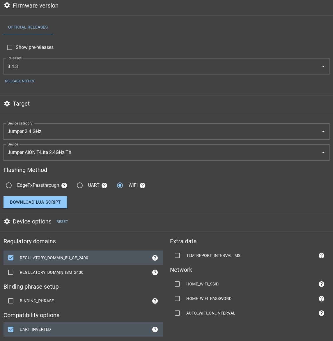
TX config
Turn on the RC, long-press the SYS button, select ExpressLRS, next scroll and select WiFi-Connectivity and click on Enable WiFi. On your computer, connect to the TX WiFi (SSID: ExpressLRS TX, password: expresslrs). In ExpressLRS Configurator, select the newest release (3.4.3 as of the time of writing this readme), and these parameters:
- Device category: Jumper 2.4 GHz
- Device: Jumper AION T-Lite 2.4GHz TX
- Flashing Method: WIFI
- Deselect the AUTO_WIFI_ON_INTERVAL
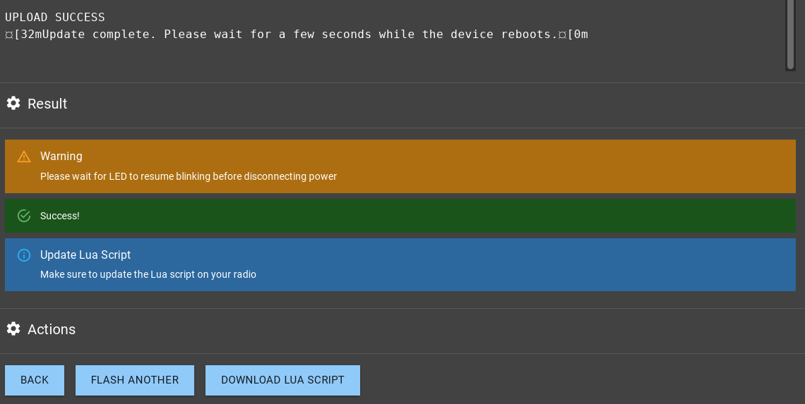
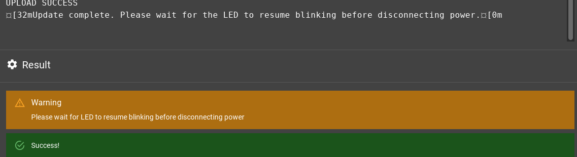
Now click on FLASH and wait until you see the Success! message:
Reboot the TX.
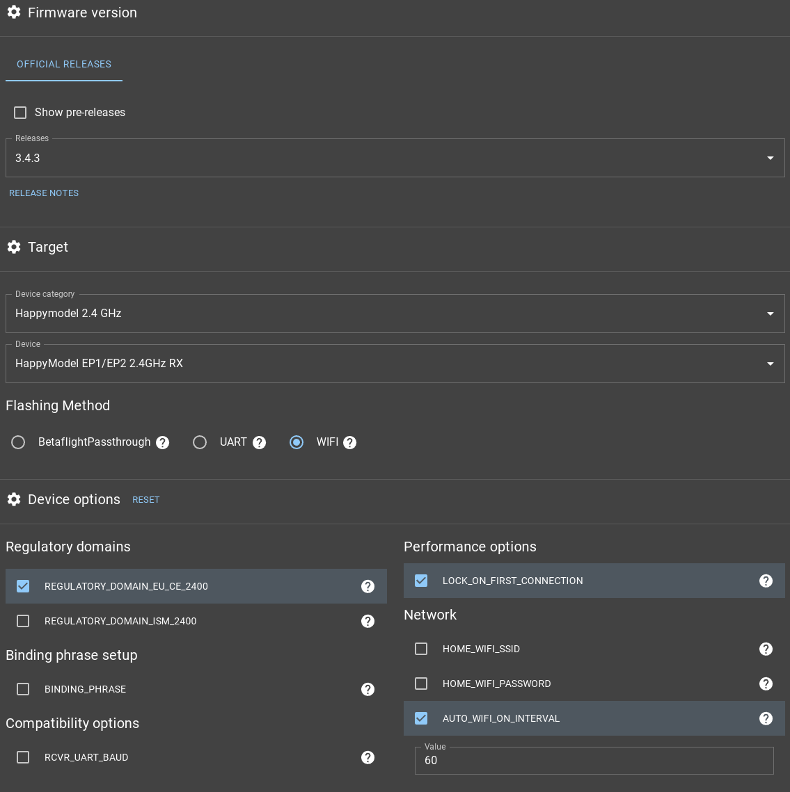
RX config
By default, the RX should start its own WiFi immediately, when it is powered on and it is not yet configured. If it was already used, it will turn the WiFi on after 60s, if it does not connect to its TX. Connect to the RX WiFi (SSID: ExpressLRS RX, password: expresslrs) and run ExpressLRS Configurator. Select the release number which matches the one you used on the TX (3.4.3 in our case) and these parameters:
- Device category: Happymodel 2.4 GHz
- Device: HappyModel EP1/EP2 2.4GHz RX
- Flashing Method: WIFI
- Keep the AUTO_WIFI_ON_INTERVAL at 60
Now click on FLASH and wait until you see the Success! message:
Reboot the RX.
Binding
We have to put the RX into binding mode (indicated by 2 blinks which repeat). To do so, we have to power-cycle the RX 3 times in a row:
- Supply power to the receiver.
- The receiver LED lights up.
- Turn it Off.
- Repeat 2 more times.
The RX should now blink like this:

Which means it is in binding mode.
On the TX, long-press the SYS button, select ExpressLRS, and select Bind. The LED on the RX should turn to solid light, which means that binding was successful. Power cycle the RX, and it should connect to the TX normally (Telemetry recovered!).
When the RX and TX are connected, we need to set the RX to output SBUS to the FCU (default is CRSF). On the TX, long-press the SYS button, select ExpressLRS, scroll all the way down to Other Devices, select it and then select the RX (usually HM EP 2400) and set the Protocol to SBUS